FUSELAGE CONSTRUCTION - Page 31.
November 27, 2003: After 10 days on the
road, I have returned for the Thanksgiving holidays and managed to get in a good SEVEN
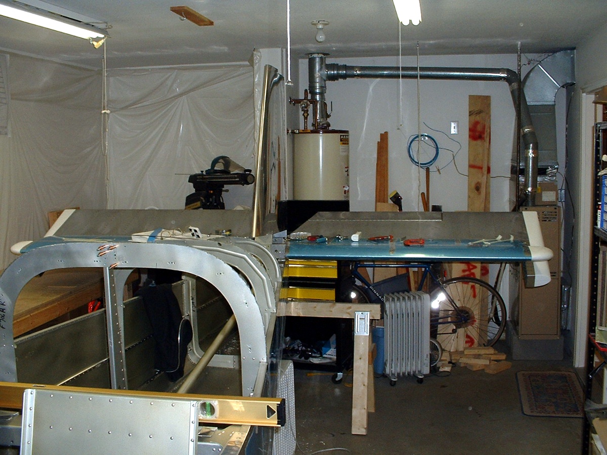
hours of work on the RV-9A today and do my laundry, too. This was another milestone
day, the attaching of the horizontal stabilizer and the first test fit of the vertical
stabilizer to the rear of the fuselage. It made for good photos! I had already
finished drilling the elevator control horns and connecting the elevator push rod to them
before I took this picture. I had to move the drill press/grinder/band saw table
away from this end of the shop to make way for the horizontal stabilizer and elevator to
attach.
Here is a side view from the kitchen door to further illustrate the accomplishments
today. That spot on the vertical stabilizer is not really there.
I did not notice it in the photo until just now, when I pasted it into this web
page. I have already removed the elevators to make some minor adjustments to the
rod-end bearings for additional clearance from the horizontal stabilizer rear spar.
I have also determined the correct number of spacer washers at the center bearing where
the elevator control arms are secured to each other. I grasped the pilot's joy stick
and found the elevators moved up and down smoothly except for a minor skin rub, hence the
rod-end bearings moved out 1/2 turn for the clearance needed.
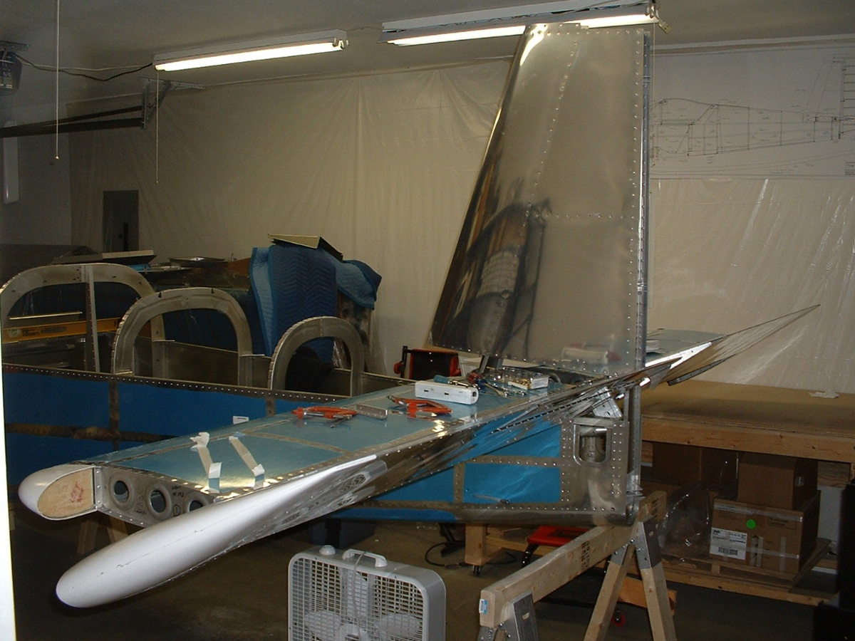
You can see that the elevator counter weights and the elevator push rod has
created an "up-elevator" condition. The counter-weights are one of the
last things to be adjusted in "FINAL" assembly near the end of the project
before flight testing.
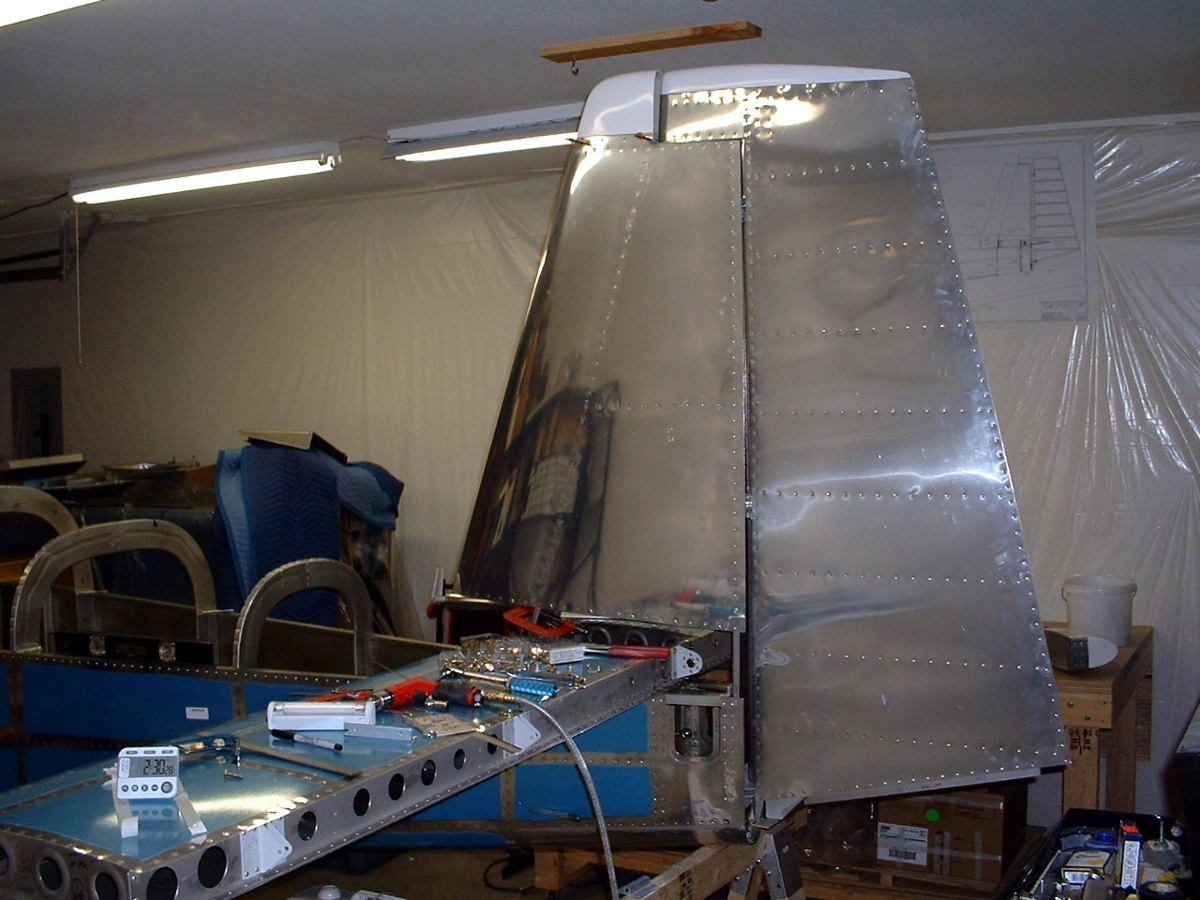
November 28, 2003: The vertical stabilizer
was fitted and attached today with some help from my neighbor, Ray Johnson.
Everything squared off nicely. The rear of the vertical stabilizer was bolted in
place and verified to have the hinge mounts to be "in line" before
match-drilling the VS attach bracket to the front spar of the vertical stabilizer.
The rod-end bearings on the rudder needed some minor adjustments to allow the bolts to
drop in place. I also fabricated the rudder stops and primed them for installation
in tomorrow's work session.
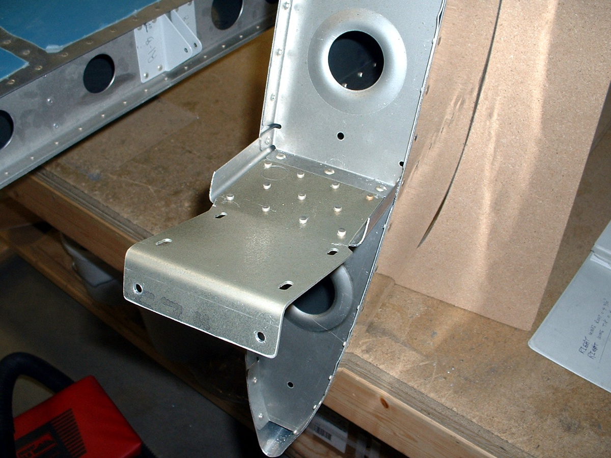
Here is the vertical stabilizer attach bracket after riveting it to the VS
front spar. (updated on December 7, 2004) There is a slight offset of the vertical
stabilizer as a result of the shape of the VS attach bracket. This was designed in
by Van's to offset engine thrust. I am told by David Edgemon that there is also a
bit of offset thrust alignment in the engine mount as well. As of this writing he
has almost 20 flight hours on his RV-9A and is finally getting all the fairings and wheel
pants in place.
November 29, 2003:
Not much time to work on things today -- only 2.1 hours. I removed the tail feathers
and put them away after riveting on the rudder stops at the back of the fuselage. I
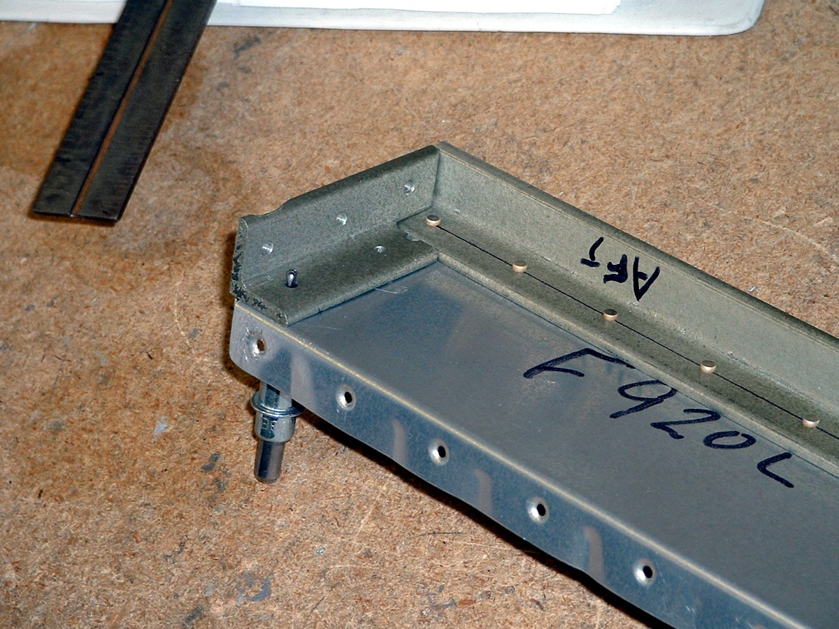
got the armrests out and managed to get one of them riveted in place. You can see
the modification I made to strengthen the armrests with 6061-T6
aluminum angle. This is the same angle stock used for the seat backs and the
main longerons -- 3/4" x 3/4" x 0.125" thick.
That short angle in the picture below will be riveted to the bulkhead behind the
seats. It holds up the long angle that runs along the "inside lip" of the
armrest. Van's design had nothing here to support the F920L armrest. I told
David Edgemon about my idea, but he used 0.060" thick aluminum angle for his
reinforcement.
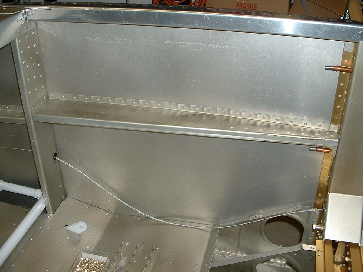
Here is how it looks installed on the LEFT side of the cabin.
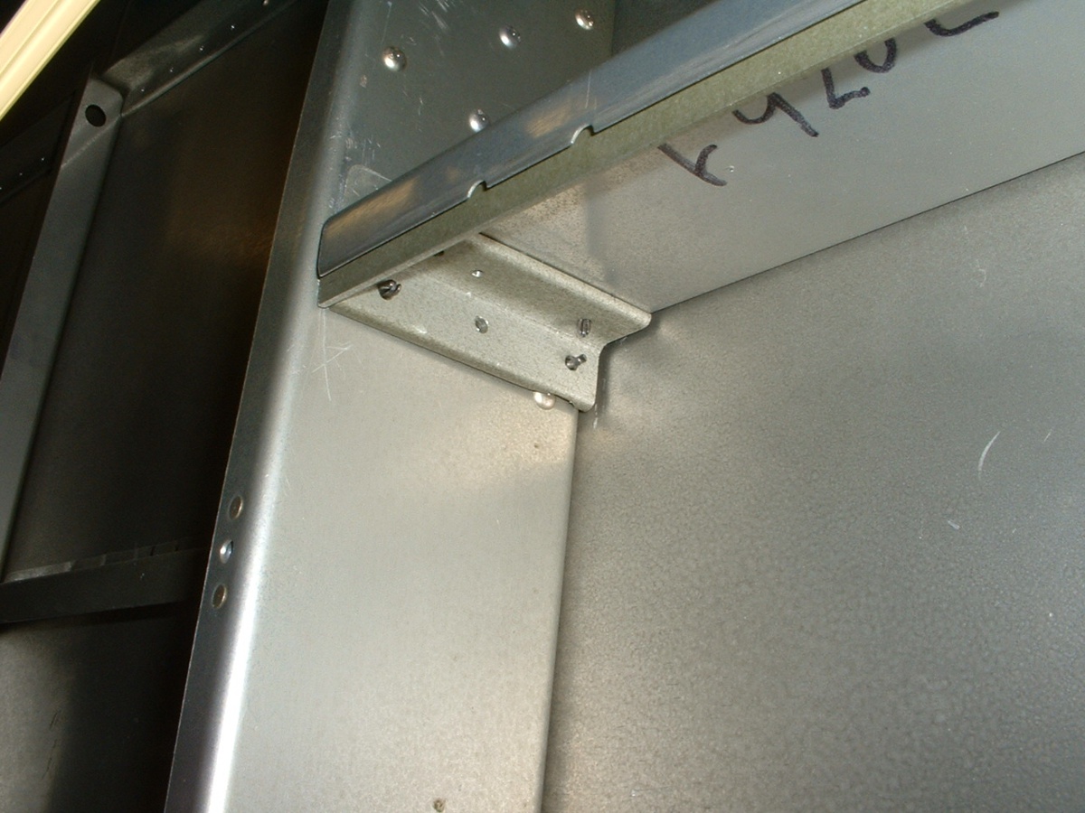
Here is the attachment at the aft end of the armrest. There was one
existing rivet here that needed to be cleared by the short angle. I ground away just
enough metal to clear the rivet. As you can see by the clecos, I took this picture
before riveting the cross brace to the bulkhead. The sequence is to rivet the short
angle in first, then put the armrest in place to put two rivets through the armrest into
the support angle. The longer angle was riveted to the armrest weeks ago using the
same hole spacing as the side skin to armrest rivet pattern. The rivets holding the
armrest to the angle are all #3's. The rivets holding the short angle brace to the
bulkhead are all #4's.
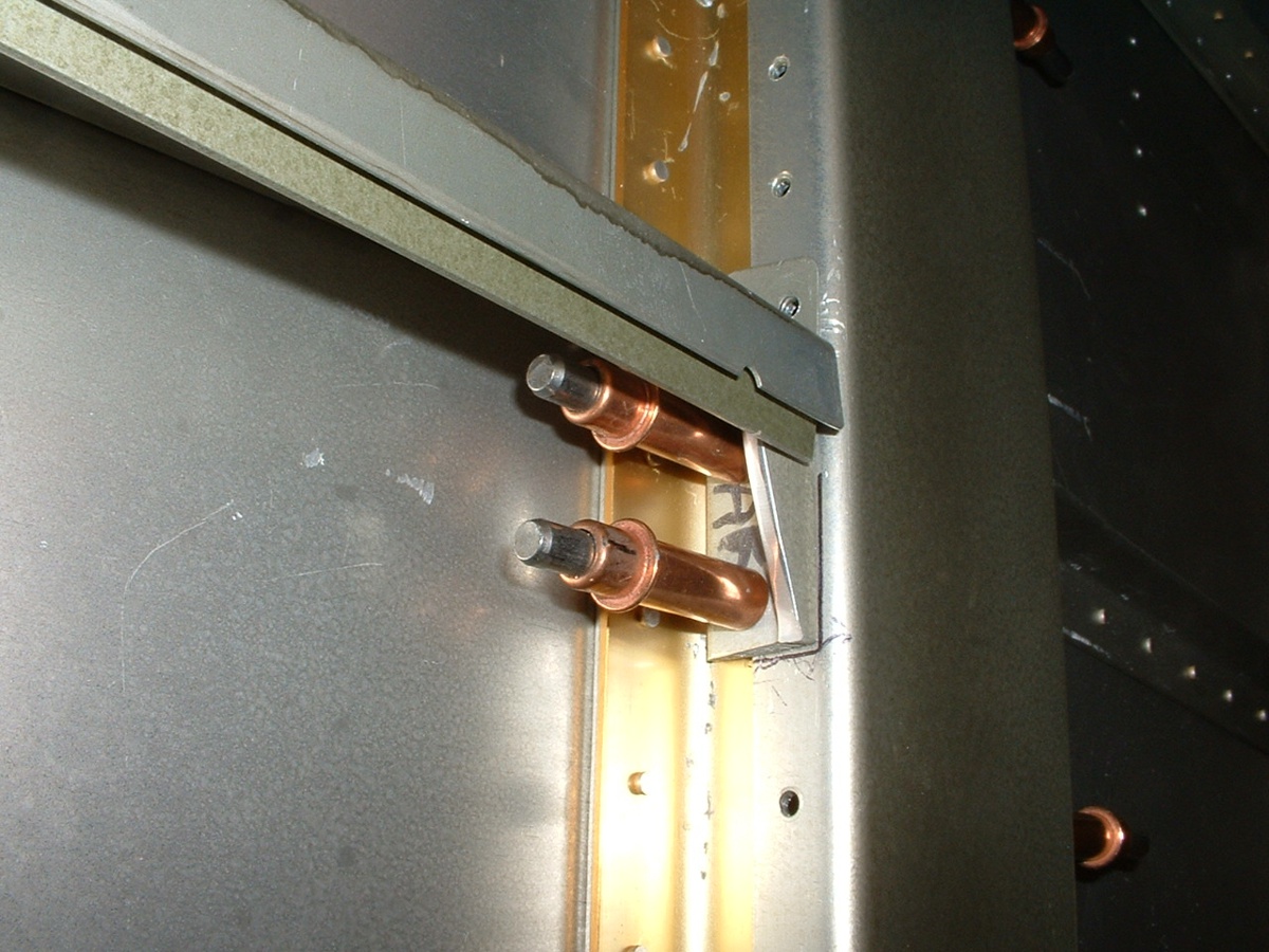
Here is the THIN front end of the armrest where I have used a shorter piece of
the same heavy-duty angle to hold up the LONG angle. This short piece will be
blind-riveted to the bulkhead when the covers are ready to be secured for the last time.
I will be using TWO 1/8" thick Cherry Max pop rivets where the clecos
are
shown in this photo.
| CLICK HERE for fuselage page 32. | RETURN to MAIN MENU |