FUSELAGE CONSTRUCTION - Page 19.
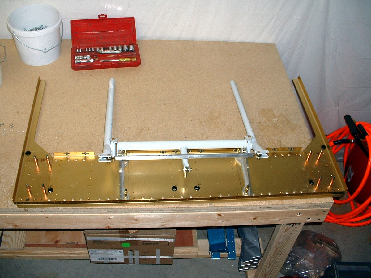
August 15, 2003: I worked on the main
bulkhead that came with the wing kit as part of a matched set with the wing spars.
Part of the work here was to modify the two machined aluminum brackets that hold the
control sticks. When I had them assembled, I calibrated the sticks to be
parallel. I have the control assembly just sitting on top of the bulkhead for this
photo.
Here you see both bulkheads and the associated parts that I worked with today
installing plate nuts and opening holes for fuel lines and electrical connections. I
also made the tubular spacers that keep the middle section bolted at the proper clearance.
I have some oak that I have to cut to the proper dimensions to represent the wing
spars when I finish bolting all this together for further assembly later with the skins
and longerons.
August 18, 2003: I finished making hardwood
spacers to represent the wing spars, then fitted the main wing attach bolts to the two
F904 bulkheads shown in the photo above. After marking all the bolts to be able to
return them to the same places, the bulkheads were disassembled and set aside. All
the non-anodized parts will be primed before assembly. Today also saw the beginning
of work on the F705, which is behind the seats and also attaches to the rear spar of the
wing to set the wing incidence when the wing is finally attached to the
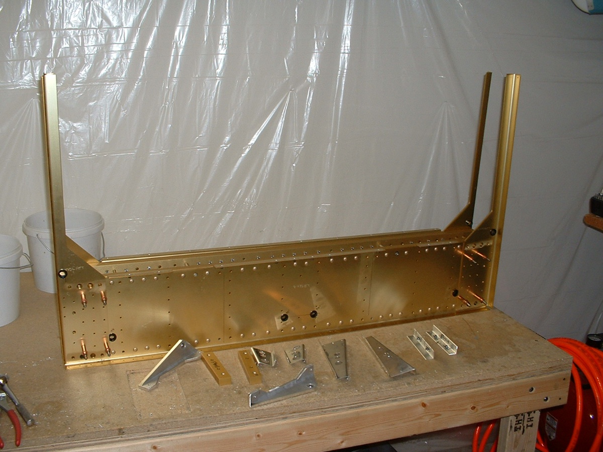
fuselage. The photo below
shows my progress as of quitting time tonight.
That aluminum bar stock running across the bottom of the assembly had no holes in
it when I started on this section. (The wide-angle setting of
the camera zoom lens makes the straight bar and table edge look bowed.) I
also fabricated two spacers then drilled and trimmed the F605C doublers that form the
attach points for the wing rear spar at the extreme left and right sides of the assembly
shown above. Those eight gray painted parts in the middle of the picture are the
steel seat belt attach brackets. They will be bolted to the F705B doubler you see in
this assembly. Total time of aircraft construction is 597.6 hours, with an additional 58.7 hours of other prep work including
unpacking, inventory of received parts, and building all the work tables, jigs, and saw
horses. Total time on the RV-9A project = 656.3 hours.
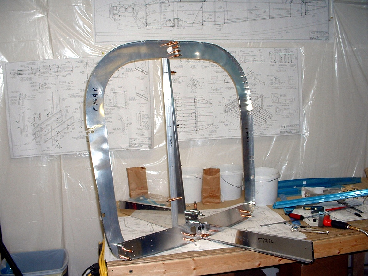
August 19, 2003: I finished the work on the F705 bulkhead group and moved on to the F706 bulkhead, which is at the rear of the baggage area. This next image below was not a part of this web page until today, September 4, 2017. I have been working on the web site to improve the image quality on the early pages of the web site. As you can see, the images are now being upgraded to 1200 x 900 pixels to make the older pages equivalent to the quality of the newer pages. When I get to those pages as part of this upgrade, I will be done with this upgrade project and will announce it on that final upgrade page.
For whatever reason that escapes me, I left the image below out of
the web site when I was first publishing this page about April 19, 2003. I
think you will understand why I did that when you see the NEXT photo below this
one. Remember that I was publishing these pages for better compatibility
with my friends who only had dial-up telephone internet access then. That
is one reason some of these early web pages did not have many photos on them.
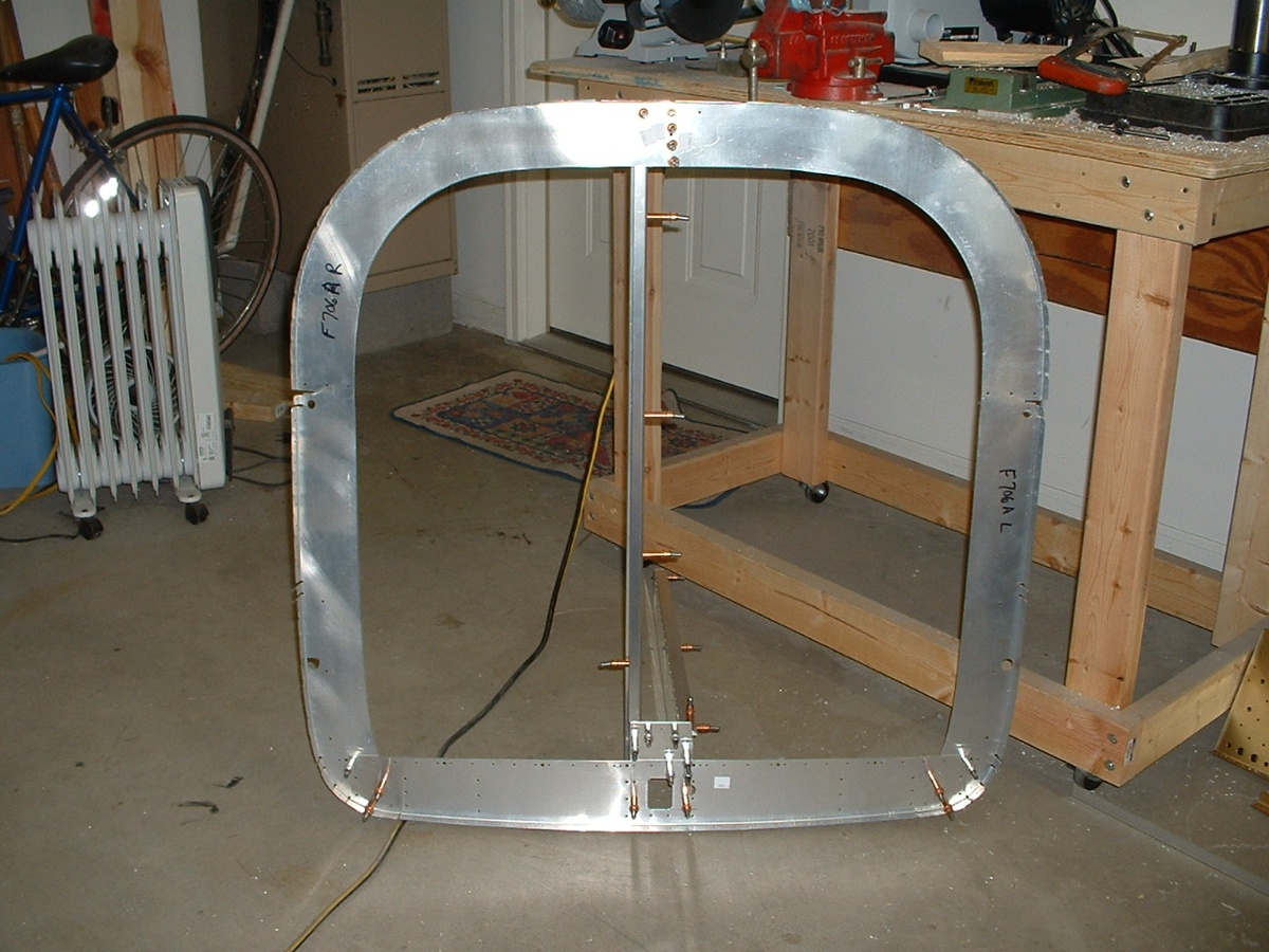
For a little background on the image above, take note of the electric oil heater
in the background. Since this page was published in August 2003, the
heater was not in service since the winter months of 2002-2003. I would
put a small electric fan behind it to help heat the garage area. I had
lined the inside of the garage door with foam insulation when the first winter
came during this construction project.
This lower part of the F706 bulkhead includes the area where the elevator push rod connects to a
bellcrank and another push rod that connects directly to the elevators. All these bulkheads
have holes and bushings for the rudder cables to pass through on the way to the tail
itself. The 5/8" bushing below is the one that allows the elevator trim cable
to pass from the baggage area sub-floor into the tail cone area.
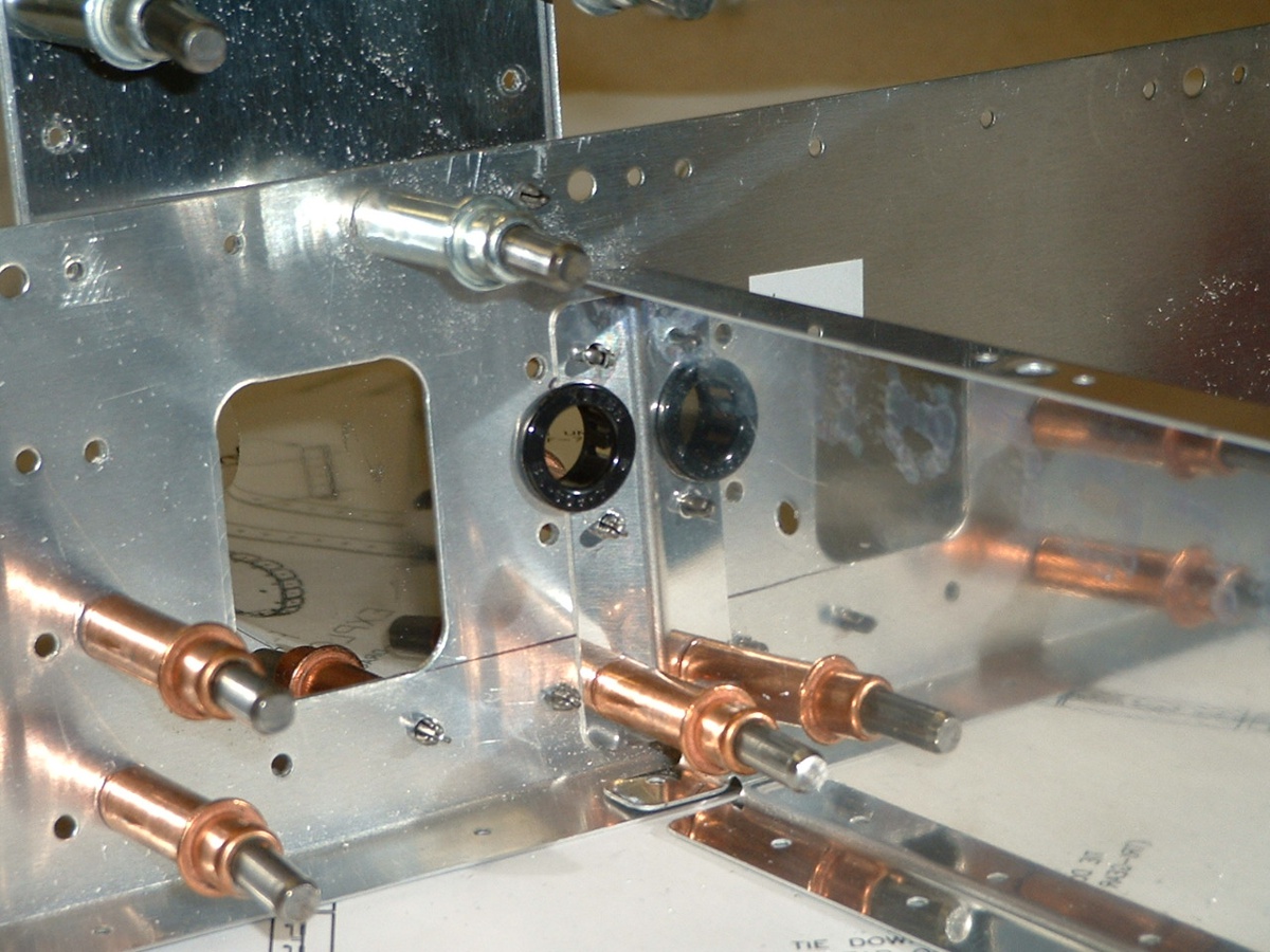
Here is the full view of the F706 baggage bulkhead. The close-up
image above is
at the bottom center of the photo below.
| CLICK for page 20. | RETURN to MAIN MENU |