David Edgemon - RV-9A at the airport.
November 27, 2004: It was a rainy day in North
Alabama and the Chattanooga area today. I took advantage of the day of no-flying to
go visit with David Edgemon while he was putting on gear leg fairings and wheel pants on
his RV-9A. Sorry, but I did not take any pictures of the gear legs or wheel pants.
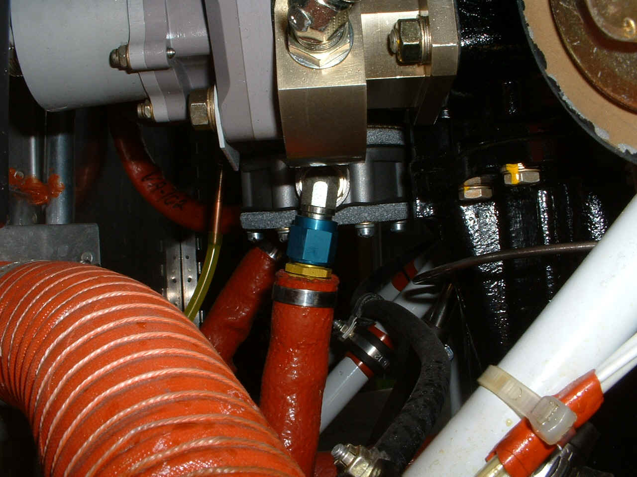
My focus was on the firewall forward installation of the various items on his
airplane that I will be facing soon. Here is one of the issues I faced when hooking
up the fuel line to the engine-driven fuel pump. David bought a special right angle
fitting to avoid the clearance of the prop governor with the fuel line.
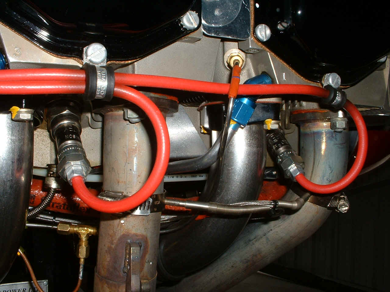
This is a shot of his intake and exhaust for cylinders 1 & 3 that shows the
primer port on #1 and EGT probes on 1 & 3 exhaust headers. That brass
"T-fitting" down in the bottom left corner of the photo is the first split of
the primer fuel line coming from the solenoid valve and going to cylinder 1 and to the
other side of the engine with another split over there going to cylinders 2 & 4.
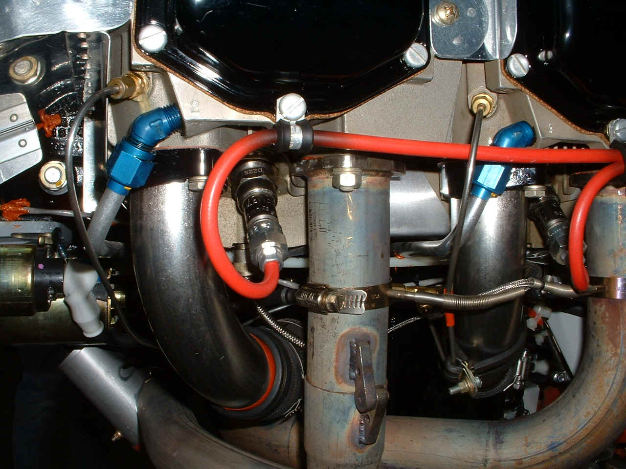
Here is the view of cylinders 2 & 4 showing the same things as the other
photo above. The brass "T-fitting" for the primer lines on this side is
hiding behind the #2 EGT probe. Take note of the "rust-colored" stain on
the exhaust header pipe from cylinder #4. It appears to be an exhaust gas leak
around the EGT probe. The time on the airplane and engine is around 12 hours when I
took these photos.
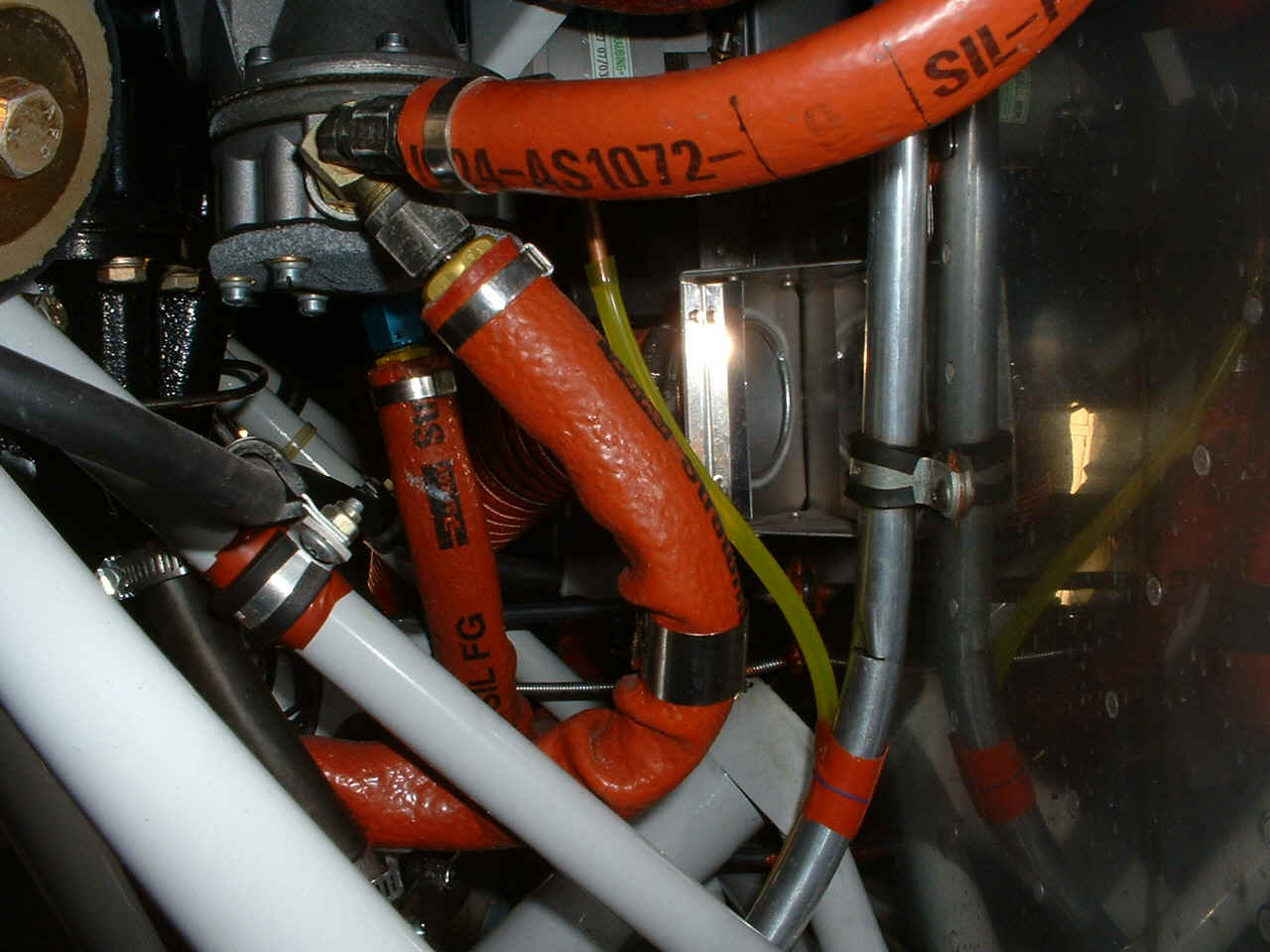
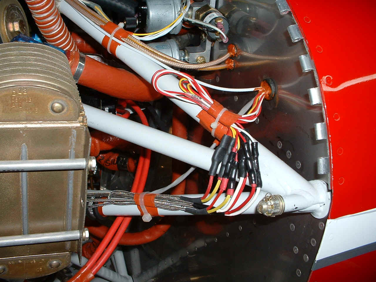
This is the output side of the engine-driven fuel pump. The overflow line
is the yellow plastic line. The aluminum crank case vent tube is attached to the
firewall and curves down toward the bottom center of the photo. David has also added
fire sleeve to the fuel pressure sensor hose going up to the right top of the photo.
The topside photo shows the back side of the constant speed prop and the
air-seal fabric that I will be installing sometime soon on my RV-9A. That RED
painted spinner cone is fiber glass from Van's firewall forward kit. Of course, it
came from Van's as bare fiber glass. David painted it himself.
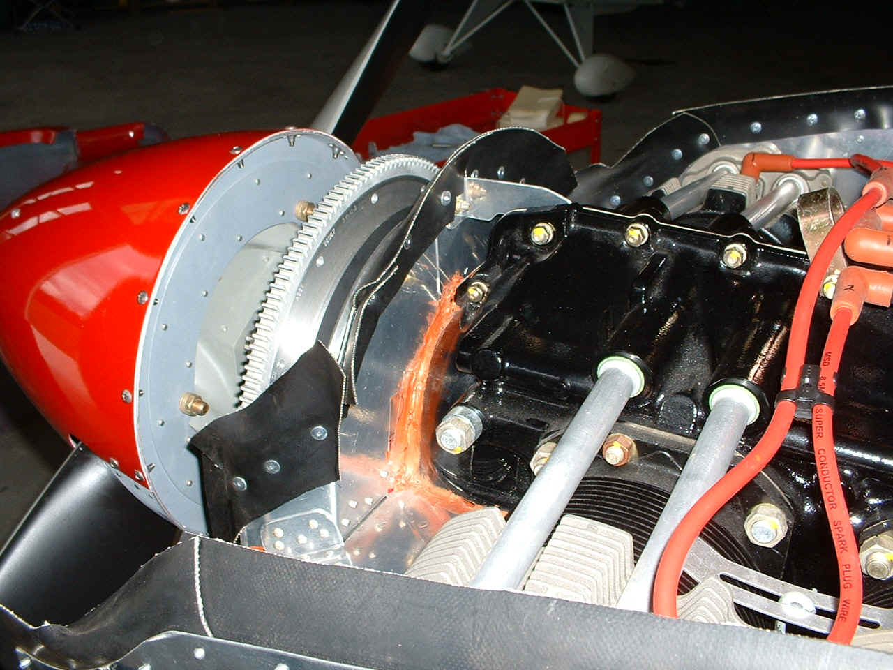
What is different here from my installation is the
addition of an oil pressure switch to drive the Hobb's meter. You can see the switch
at the right center of the photo on the sensor manifold adjacent to the oil pressure
sensor. The switch has both normally closed and normally open contacts. It can
turn on the Hobb's meter when the engine is producing more than 25 PSI oil pressure.
And of course, it can also drive a warning light of low oil pressure in the other switch
condition. David has also added a metal assembly above and in
front of the oil cooler to keep the airseal fabric straight across the back of the engine.
It is visible in the center of the photo with 10 pop-rivets in its top surface.
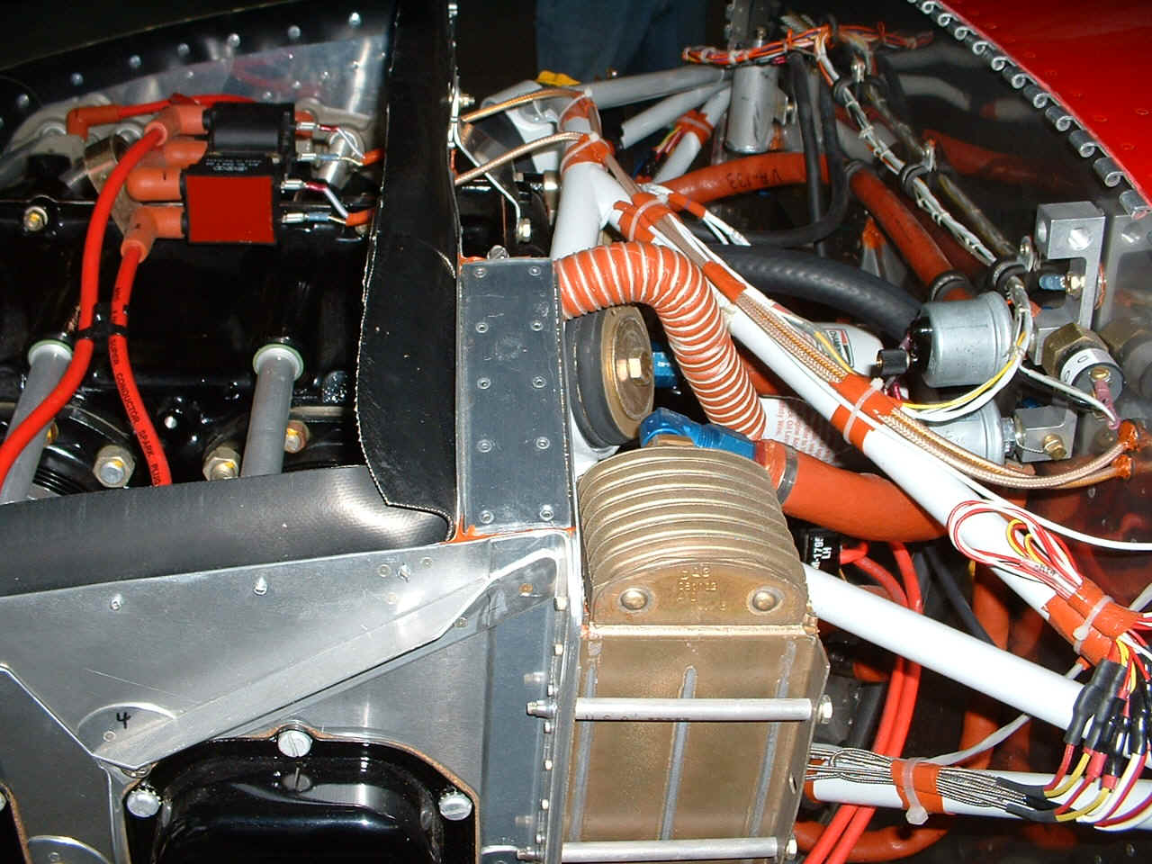
This picture reminded me that I need to seal the heat-shrink material on my own
EGT & CHT probe connections. Notice how David has put some tape on the wires and
the steel engine mount tubes where the wires are tie-wrapped to the engine mount.
This will minimize the chances of damaging the wires over time with engine
vibrations. A good idea that I will add to my installations.
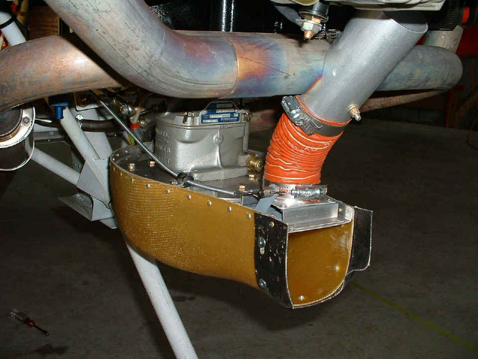
The filtered-air-box (FAB) will soon be on my agenda. I
also have to order the carb heat muff and connector that fits on the top side of the FAB
assembly. That is the up-draft carburetor in the center of the photo.
| Return to Menu Page. |