Wendell Folks RV-8 Project - Page 71.
November 26, 2007: The Monday evening
session was all about getting the wing bolts installed into the right wing that was fitted
to the fuselage last night. I demonstrated the procedure to Wendell on the first two
bolts, then got out of his way as he crawled inside to finish the job. And then the
second wing was installed and the bolts started going in quickly. I demonstrated the
technique of using the smaller hardware store bolts for the initial alignment, then the
precision bolts were installed. First one upper, then one lower bolt were installed
using the hardware store bolts. You can see how the threads were ground down to make
a smooth "drift pin" to push through the wing spars and the fuselage wing spar
assembly. After that, one precision fit bolt was installed adjacent to the store
bolts. Then the store bolts were removed and the remaining precision bolts were
installed.
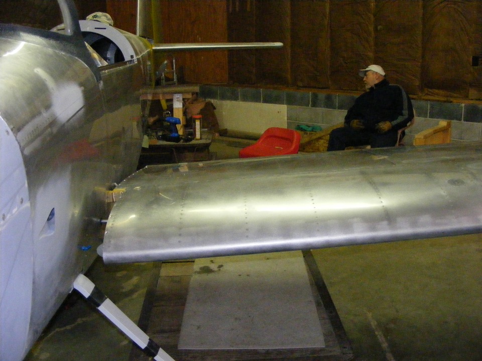
Wendell's friend "Cool" was there to lend a hand as needed. It
was much easier putting in the LEFT wing tonight with that extra person. I was
prying the fuselage spar assembly apart to accept the wing spar and doublers from the LEFT
wing. Once the wing was partially inserted, it went into its proper position quickly
and the bolts were installed in short order.
I finished the evening session with a preview of tomorrow's tasks for Wendell.
It is all about wing incidence and sweep. For now, he has some chores to do
tomorrow and then I will help him drill the rear spar wing attach bolts to the bulkhead
tabs sticking out of the fuselage sides. After that is done, it is time to start
plugging in wing wiring connections and connect the aileron push-rods to the joy stick
assembly. And more and more...
November 27, 2007: The
evening session tonight was about getting the wing bolts installed at the rear main spar
and fitting the brackets to the fuselage sides that secure the inboard nose ribs of the
fuel tanks. Wendell fabricated these brackets a few months ago. Tonight they
were drilled to fit the airplane. Due to limited space INSIDE the fuselage, they
could not be match-drilled from the INSIDE in the same manner as I did with my RV-9A.
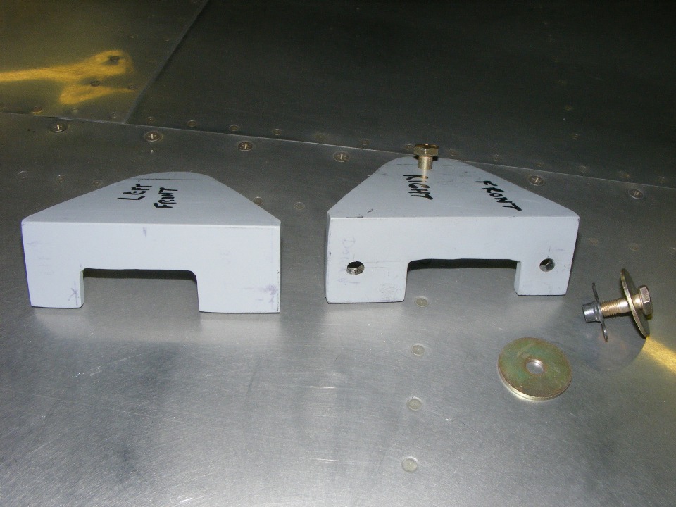
This was the first attempt at drilling the two holes that will mate with holes in
the fuselage and the steel doubler inside the fuselage adjacent to the gear leg tower
assembly. These holes were at the correct height and spacing, but later needed to be
slotted slightly to get the fit against the mating bracket seen in the NEXT PHOTO below
this one. The initial location for the holes was determined by clamping each bracket
to the one on the inside rib of the fuel tank. With the bracket pressing against the
side of the fuselage, lines were drawn on the fuselage skin. After the bracket was
removed, the distance from the line to the hole in the fuselage was measured and
transferred to the bracket before drilling the two holes you see in the photo below.
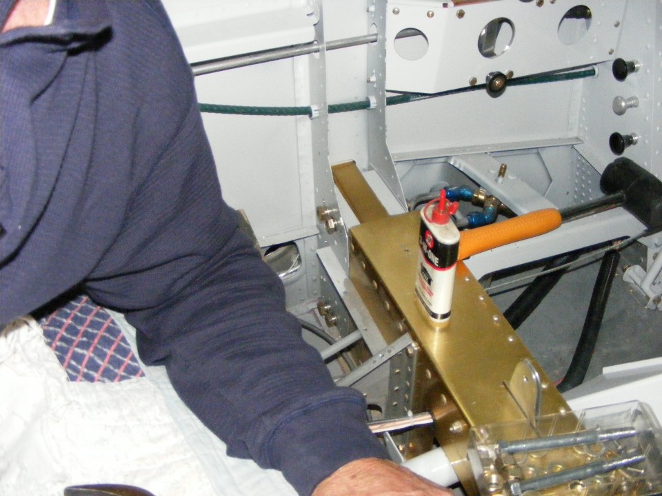
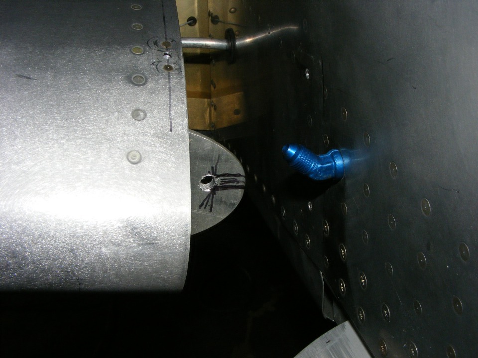
This photo shows that fuel tank bracket that came already mounted to the fuel
tank as part of the quick-build wings. The blue vent line fitting going into the
fuselage is actually just slightly forward of the bracket. The horizontal lines I
have drawn on the bracket show Wendell where to slot the bracket for safety reasons.
Van's has designed the part to slide away in the event of an off-airport crash
landing. The idea is the wing could be bent backwards without the fuel tank being
ruptured and creating a fire hazard. The part is designed to slide away from the
fuselage in that event, but normally be stable in the vertical plane. That means we
are providing support for the 20 gallons (120 pounds) of fuel that could be inside the
fuel tank when it is full of 100 Low-Lead AVGAS.
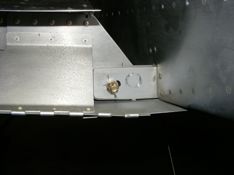
At the rear spar of each wing is the 5/16" bolt that sets the wing
incidence and sweep of each wing. The shiny circle is from the C-clamp that held the
wing in the correct location while the bolt hole was match-drilled in the rear spar and
doubler that is between two 1/4-inch thick bars sticking out of the sides of the fuselage.
I had drawn some marks on the bars indicating the acceptible location range for the
bolt. The two straight lines establish the center of the vertical range and outer
limit of the hole position in the lateral domain (UP/DOWN & LEFT/RIGHT). The
round spot was where I thought the bolt would go until I realized the clamp was in the
way. Wendell got as close as he could within the acceptable range to drill the hole.
By the end of the evening session, the pitot tube pressure line was connected
and secured from the wing to the fuselage. The matching electrical plugs for the
wing leveler, Dynon remote magnetic sensor, landing lights, and strobe lights were all
connected to the LEFT wing. Wendell had his instructions on completing the fit of
the fuel tank attachment brackets to the fuselage sides.
| CLICK for Folks PAGE 72 | Return to Other RV Menu | Return to Main Menu Page. |