Wendell Folks RV-8 Project - Page 68.
November 17, 2007: Finally, a Saturday
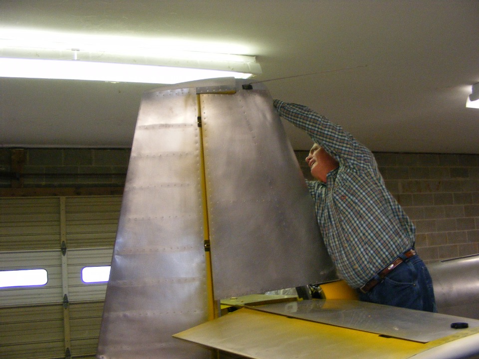
afternoon session with Wendell with some real milestones to report. Wendell wanted
to double check the clearance of the rudder counter weight from the fiberglass cap on the
vertical stabilizer before we glass in the balsa block that will seal the aft side of the
cap behind the VOR antenna.
Before the rudder went on, I had pointed out that the tail light B+ wire was caught between the rear spar of the vertical stabilizer and the last bulkhead of the fuselage. After that little snafu was corrected, the ground wire to the tail light was installed on one of the three bolts that had to be loosened to free the power wire to the light. A layer of twist wrap plastic was wrapped around the strobe power wire and both wires that go to the tail light bulb which will be mounted in the fiberglass lower rudder cap.
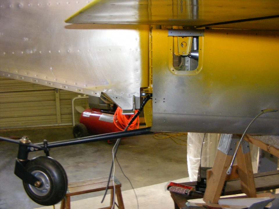
The elevator pushrod is in position again but does not have all the spacer
washers installed yet. I reviewed the blue prints with Wendell to be sure he
understood just how many washers were needed, their type and sequence of installation at
the center bearing of the horizontal stabilizer and the ends of the elevator control horns
seen in this photo.
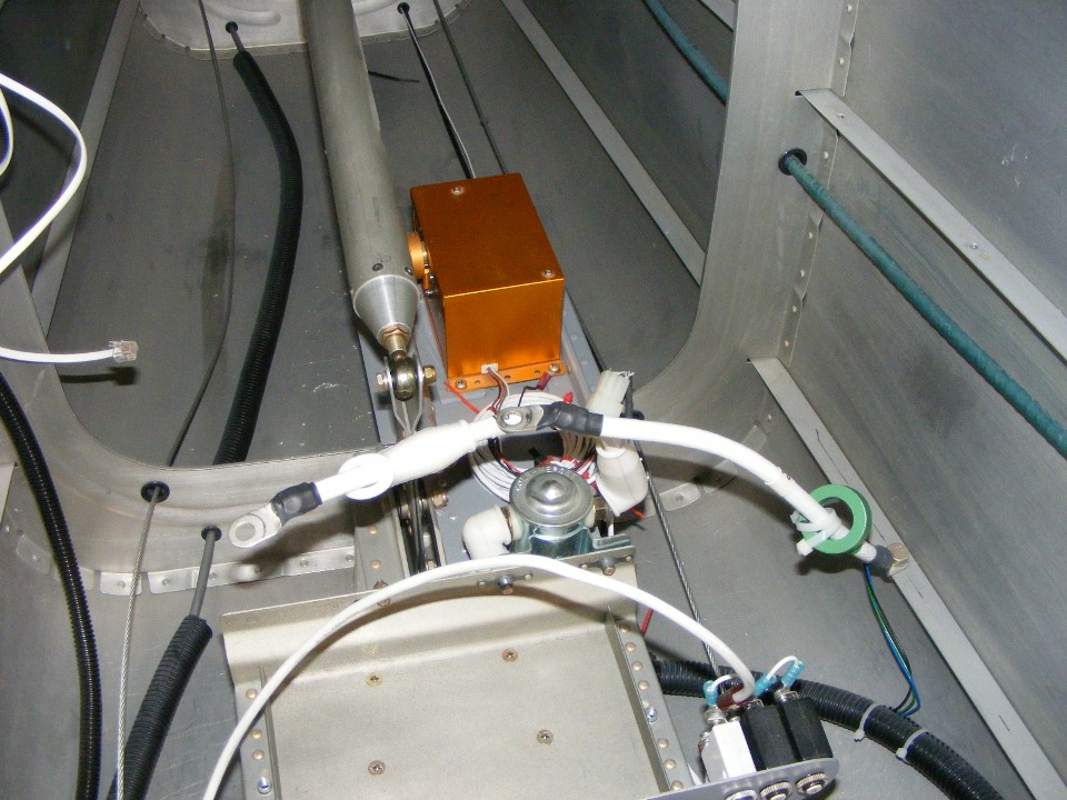
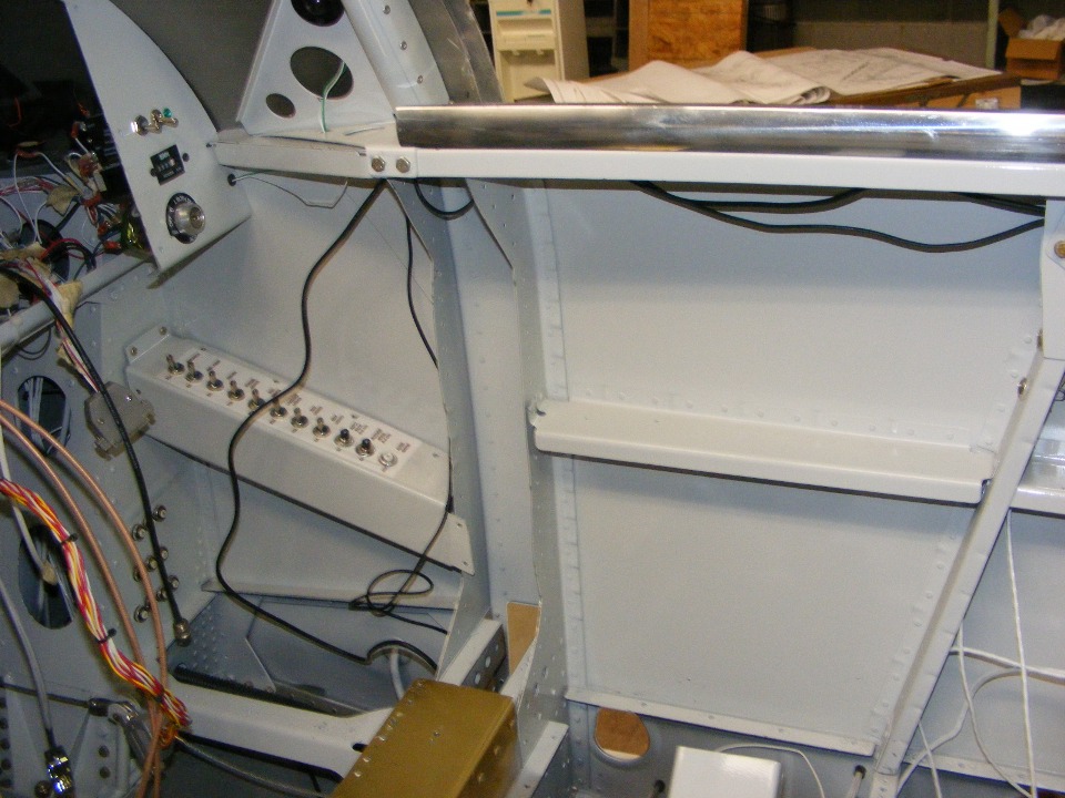
The altitude hold servo motor is now back in position and connected to the
wiring harness from the instrument panel. Wendell had done this work earlier in the
week. Notice the black RG-58 coaxial cable and the white 12-volt power wire running
aft from the servo area. The coax cable runs from the VOR antenna to the instrument
panel. The tail light strobe cable is inside the corrugated flexible conduit on the
left side of the elevator push rod.
Here is a view showing the temporary location of the steel mounting plate and
the GPS and XM Satellite weather antennas. The cables going from them to the
instrument panel are seen below the right longeron. I gave Wendell instructions on
how to secure the cables as part of his assignment for the coming week. His paint
shop guy will have to come over again to paint the steel plate and the fuselage skin under
the plate before it can be installed permanently. The GPS antennas are located
inside the aft canopy area when it is closed.
Here is the view of the GPS cables running forward. Since the GPS antenna
cable has a BNC connector on its end, the cable will not go through the instrument panel,
but just below it. Speaking of wires, I did not take a relevant photo, but the light
wires to the magnetic compass are now secured under the forward top skin above the radio
stack area.
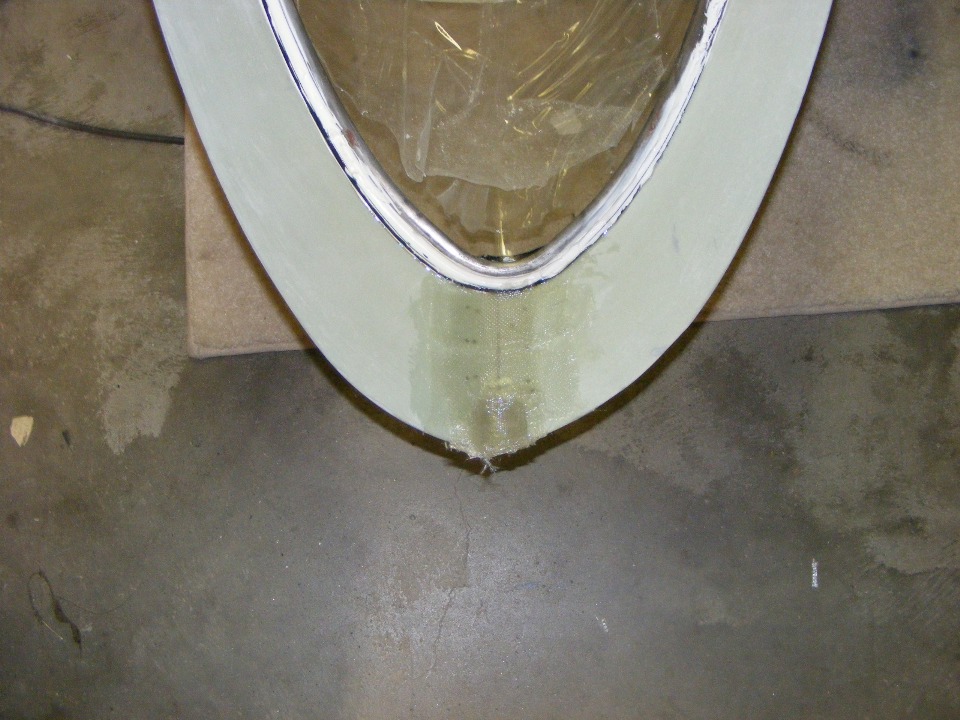
We mixed up some epoxy to work on the lower rudder cap preparations for the aft
tail light and strobe assembly. Wendell wanted to add some additional glass layers
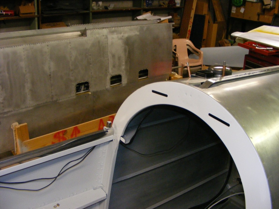
to the rear joint where the canopy skirts meet behind the bubble canopy. This photo
shows the inside of the canopy skirts at the rear of the canopy frame. One of the
things that will be happening soon is the painting of the inside of the canopy skirt and
frame to match the interior cabin wall colors.
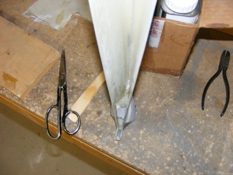
This is the aft end of the fiberglass cap for the bottom of the rudder. A
hole to accept the strobe light assembly has been cut into the fiberglass and two screw
holes have been drilled to secure the assembly. This photo shows how gray electrical
tape has been put across that large 1-inch-plus-sized hole and the two screw holes.
A slurry of tissue paper mixed with epoxy resin has been placed over the inside of
the screw holes to accept the #4 mounting screws that will secure the strobe light
assembly. After curing for a few days the light will be placed into the large hole
and the screw holes will be match-drilled and tapped with a 4-40 tap to accept the screws.
This is the same process I used to mount my tail light on my RV-9A.
| CLICK for Folks PAGE 69 | Return to Other RV Menu | Return to Main Menu Page. |