Wendell Folks RV-8 Project - Page 55.
June 2, 2007: This was the day the baggage
door skin got riveted to the ribs, the doubler around the lock, and the hinge and angle at
the upper end of the door. I also showed Wendell how to form the end of the hinge
pin for the baggage door to allow it to be removed if maintenance is required. I did
not take a picture of that today, but I am sure we will find time to do that before the
other half of the hinge gets riveted to the fuselage skin and the doubler that connects
the firewall and first bulkhead together and supports the door. The inner skin to
the door was clecoed to the ribs to be sure the fit was correct. As it turned out,
some of the inner skin had to be filed away to get the desired fit.
At the end of today's session, Wendell started talking about the oil door work to be done soon. We talked about how and where the fiberglass cowl has to be trimmed to make way for the hinge and door. I will have some interesting photos for you when that work gets under way. Wendell wants to do a push-button latch assembly similar to the one on the Cessna 182 instead of the method normally used by Van's on the oil doors.
June 4, 2007: Wendell showed me his baggage door
where he had installed the two latch rods to the key lock assembly. Our attention
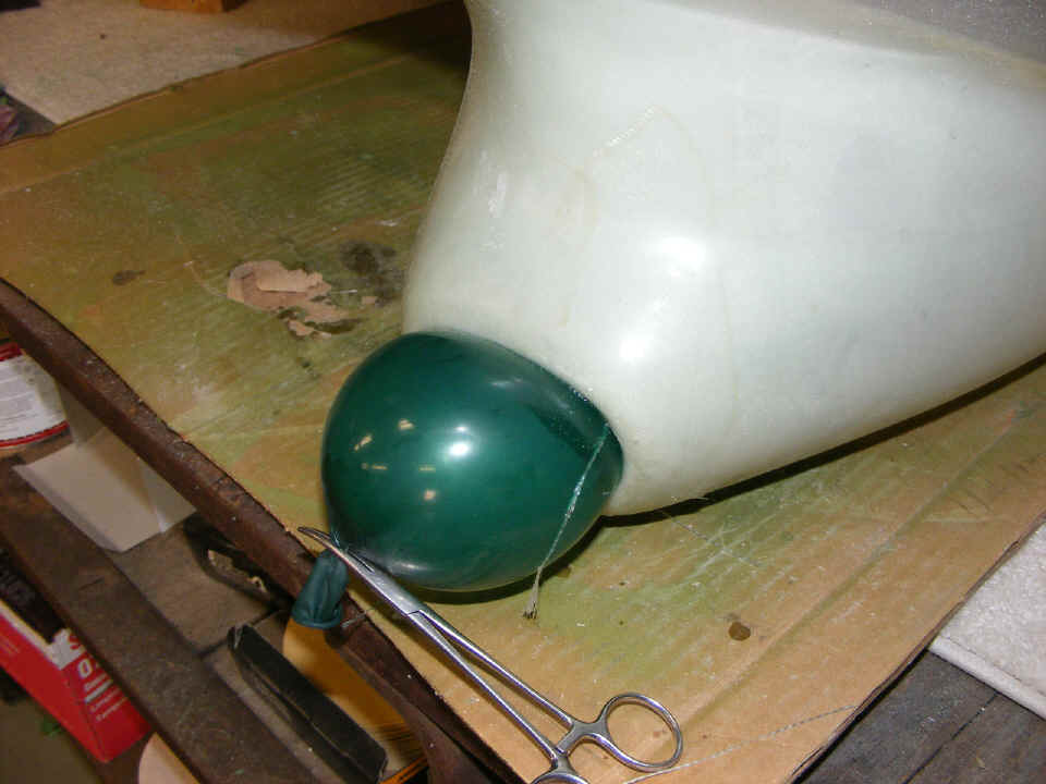
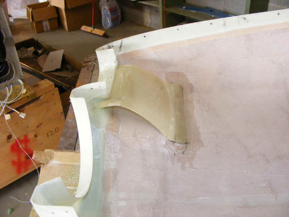
then turned to the completion of the fiberglass work for the carburetor air inlet scoop.
A new layer of glass and resin was added to the inside of the existing two layers
of glass added previously. A new balloon was inflated to insure a smooth inner
surface to this new work.
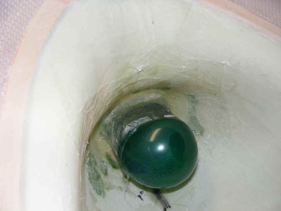
An additional layer of glass was put on the inside to fix a bubble area from
the previous extra layer of glass added here. The balloon must be inflated to extend
on both ends of the air duct. This assures a good fit of the new layer of glass to
the inside of the existing duct work.
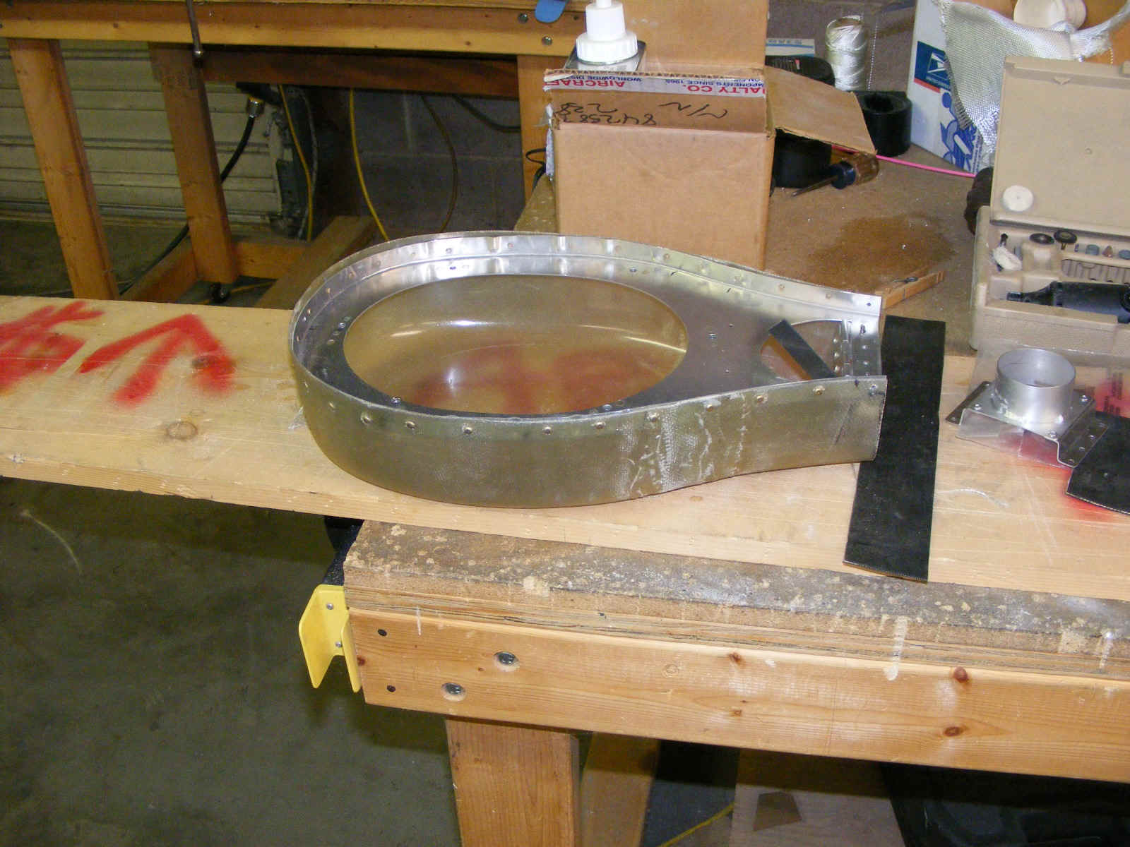
June 5, 2007: Wendell
worked on the filtered air box by riveting the fiberglass bowl to the metal plate that
interfaces with the carburetor.
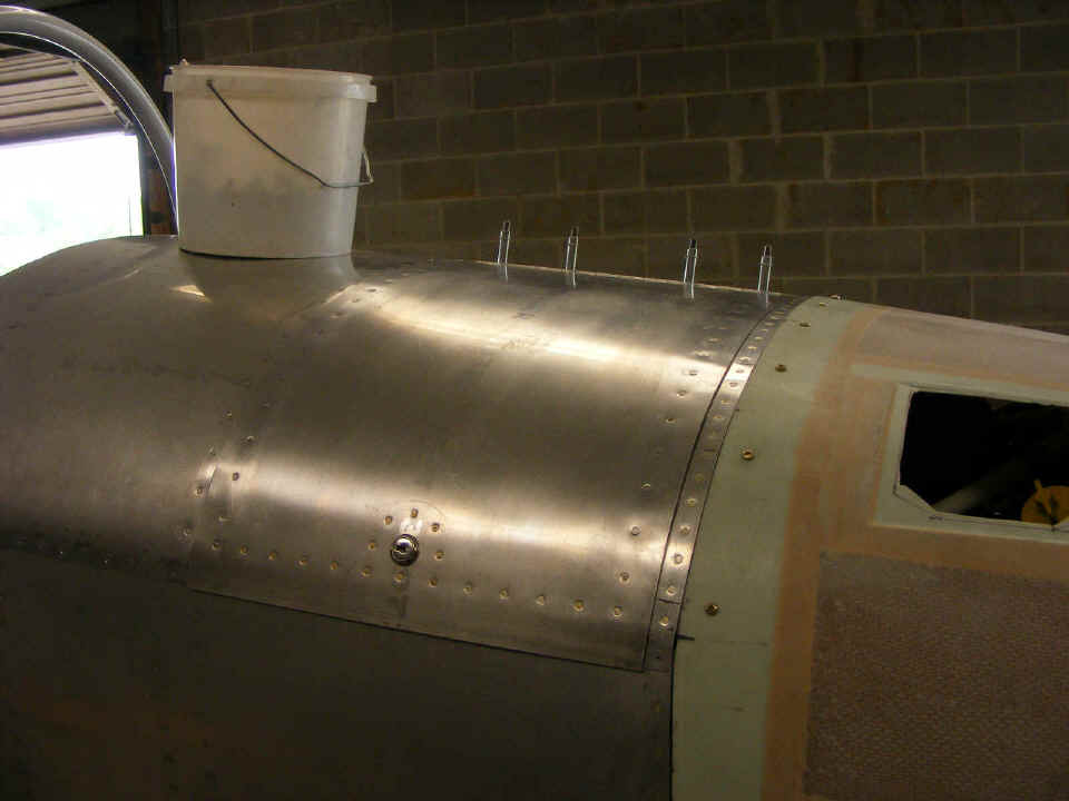
The ramps on the upper cowl were glassed into position earlier today.
They had previously been epoxied in place with clecoes. Today a layer of 9-ounce
glass cloth was put in position at the air inlet and the upper end where the ramp meets
the upper cowl.
The FAB bowl is riveted except for the two front rivets where the air seal
fabric will be installed. I gave Wendell instructions on how to install the fabric
and the carb heat door hinge with the vent. He will be taking his Cessna 182 to
Murfreesboro tomorrow for an assessment. A prospective buyer is coming to see it
when the airplane gets its annual inspection next week.
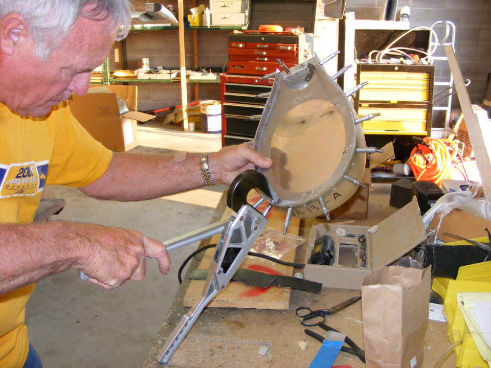
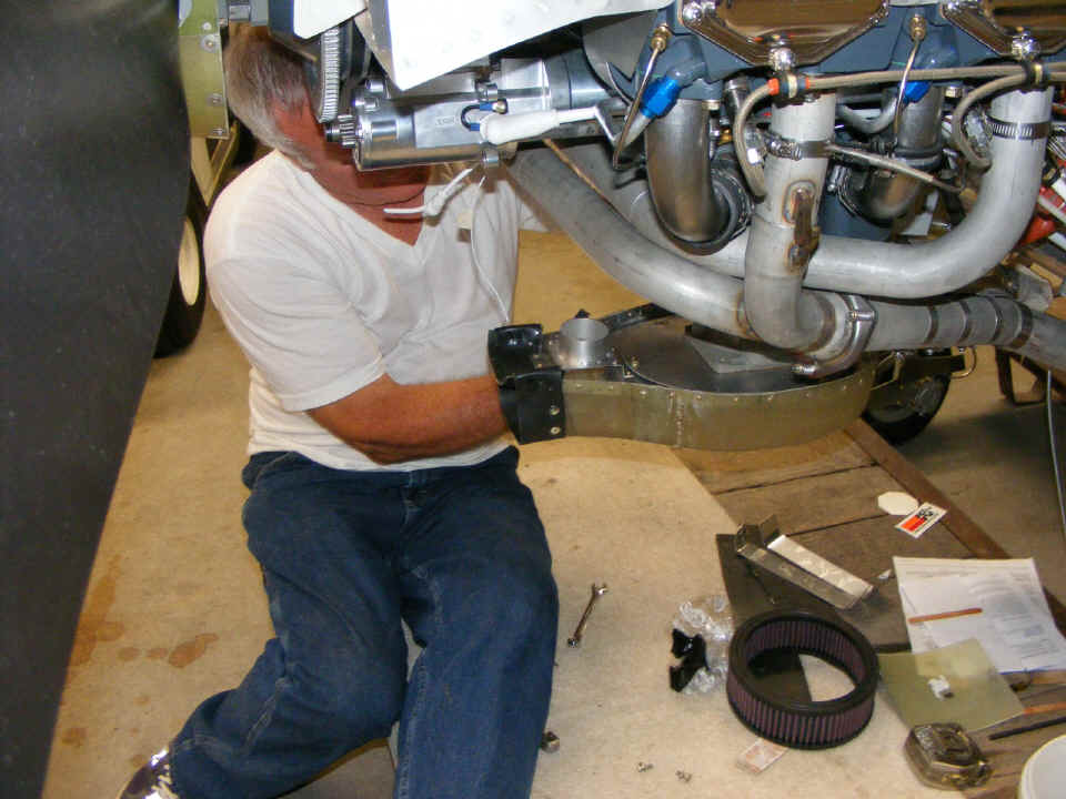
June 6, 2007: This was the night the FAB was
completed. Here you see Wendell putting the box on the carb for the final check of
the air seal fabric with the lower cowl fiberglass inlet. One quick trim on the
lower part of the air seal fabric was all it needed for a perfect fit.
After the FAB air seal test was completed, I had him cleco in the fabric sections that will fit from the lower cowl to the front lower cooling baffle ramps. A few minor adjustments were needed before I drew in some lines on the fabric where the best fit to the baffle occurred. Those aluminum clamp plates and the fabric strips will be finished in the next session. We knocked off tonight's session just a few minutes before 10 PM.
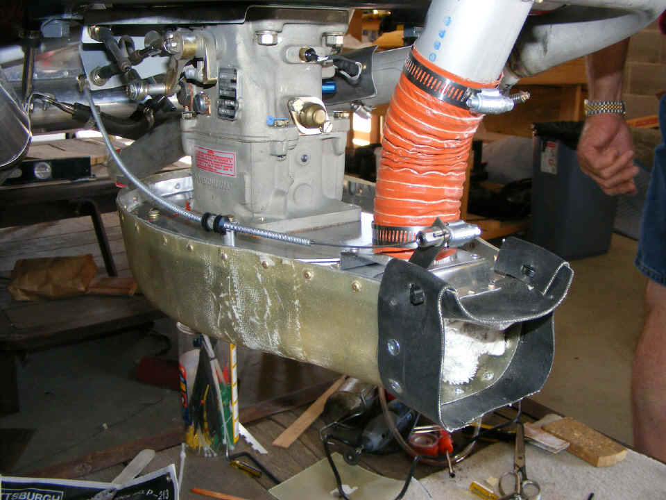
June 9, 2007: The
Saturday session with Wendell found the completion of the work on the filtered air box
with the connection of the carb heat control cable to the door up front. The SCAT
tube to the carb heat muff on the crossover exhaust pipe from the number one cylinder is
now installed. The towel in the front of the FAB is there to keep insects out of the
carburetor. The carb heat door is UP to keep them from getting in that way.
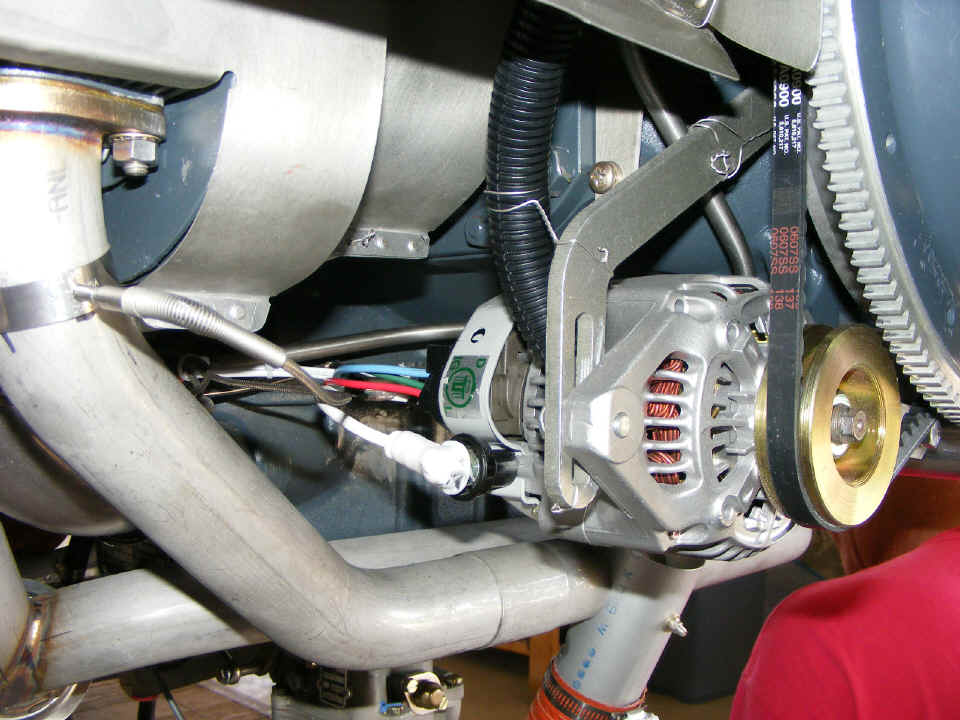
The other thing finished up front on the engine is the connections to the
alternator for the DC output power cable, and the field cable from the control panel
switch.
| CLICK for Folks PAGE 56 | Return to Other RV Menu | Return to Main Menu Page. |