Wendell Folks RV-8 Project - Page 46.
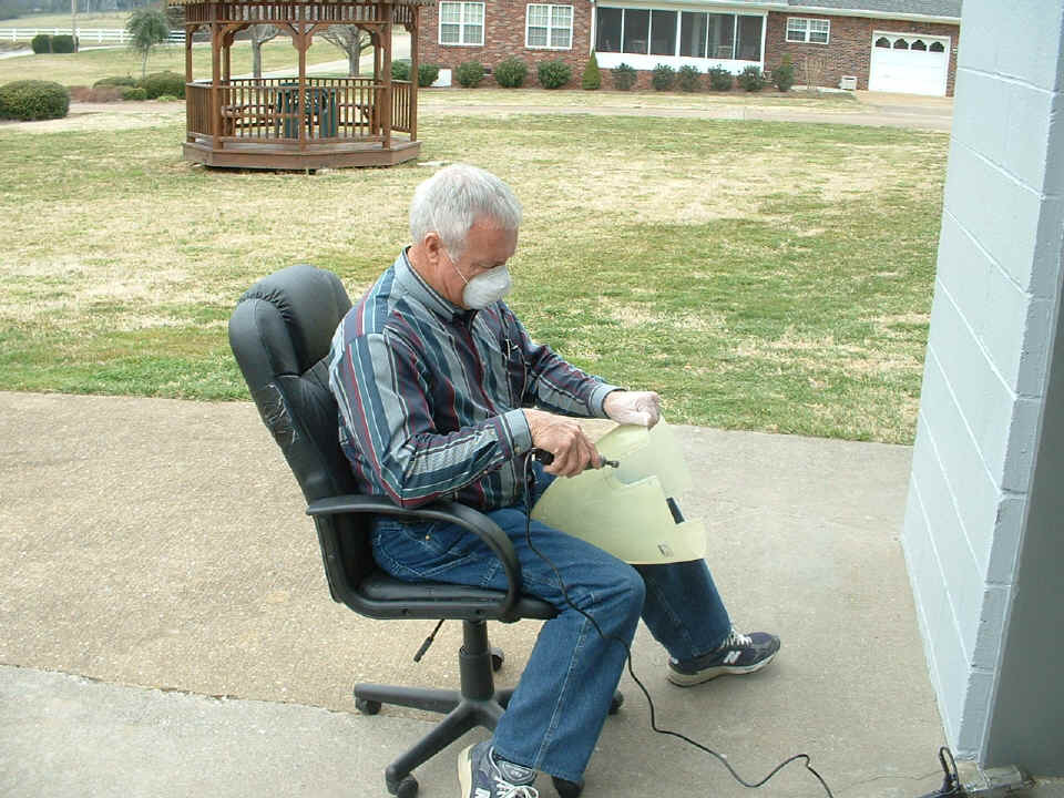
March 10, 2007: The Saturday session found
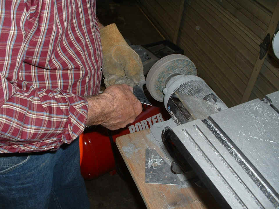
Wendell working to cut the spinner fiberglass "bowl" to clear the propeller
blades. The Dremel tool with a miniature sanding drum makes quick work of removing
excess fiberglass as needed. He had already removed much of the excess fiberglass
from the upper cowl before I arrived after lunch for our usual Saturday afternoon session.
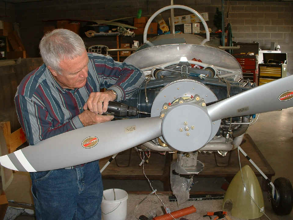
As part of that process, the propeller blades were twisted by hand to be sure
the cutouts in the bowl were adequate to allow full propeller pitch control as needed in
normal flight operations. Here is a shot of Wendell drilling the first holes for the
screws and nut plates that will finally secure the bowl to the back plate. A #40
drill bit was used for the first holes in the rear and front plates. The fiberglass
bowl was then fitted in position with a light shining through the holes from behind.
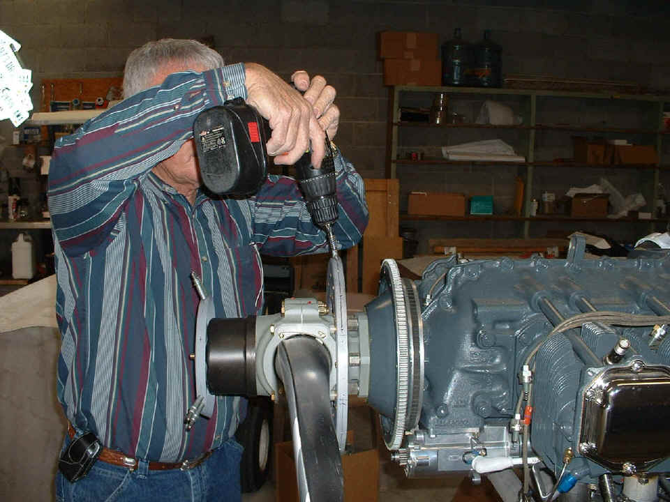
The bowl was match-drilled to the back plate, then the front spinner plate was
marked at six evenly-spaced locations in preparation for drilling the holes there.
With the bowl clecoed to the larger rear plate, the front six holes were also drilled with
the #40 drill bit. After that, half of all the holes were drilled to final size to
accept #8 screws.
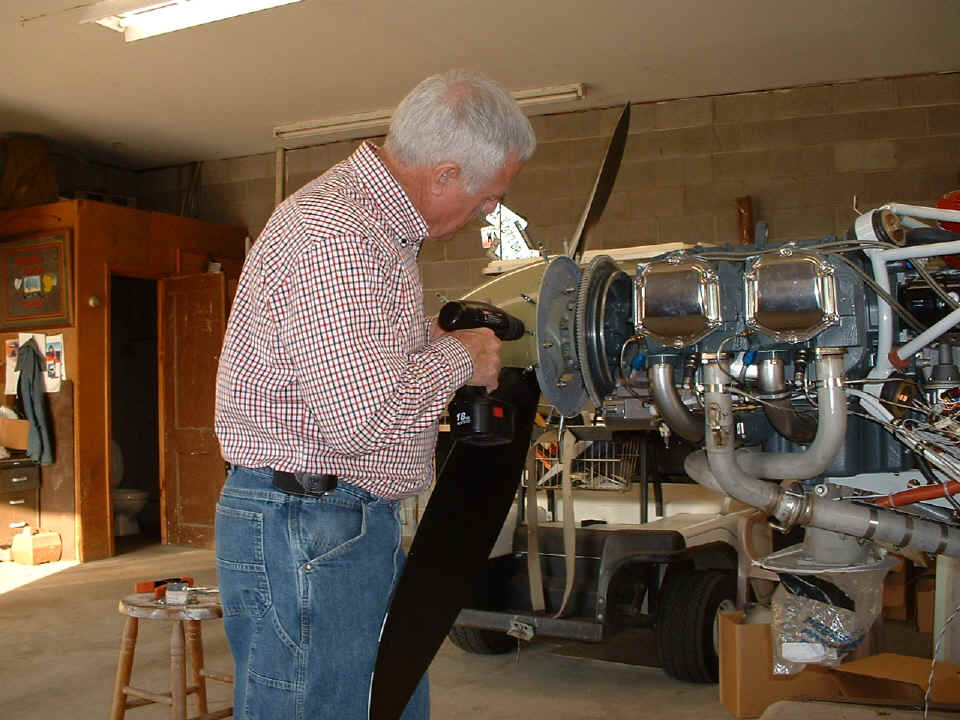
I forgot to take a picture of the spinner after the final fitting was made and
the fiberglass "bowl" was drilled and clecoed to the spinner back plate and nose
plate in front of the prop hub. After the screw holes were laid out evenly in the
photo above, a plate nut is used for back-drilling the rivet holes to secure the plate
nuts. Three plate nuts are already clecoed to the front plate as Wendell begins
drilling rivet holes for plate nuts to be added to the spinner back plate.
Deburring, countersinking, and riveting of the plate nuts will be in the next
session. When those are completed, screws will be used to secure the bowl to the
plates, then the other half of the #40 holes will be enlarged to accept #8 screws, plate
nuts, etc.
After the propeller was mounted in the previous session, there will be several milestones coming in rapid succession in the upcoming weeks.
March 11, 2007: A
Sunday afternoon session was all about getting the fiberglass spinner shell drilled and
countersinked to accept the #8 flat head screws and Tinnerman washers. About half of
the screw holes had already been drilled to screw size. Plate nuts were added to
those locations, then the shell put back on the prop with the original clecoes in place.
The shell was then countersinked to accept the flat head screws and washers.
After all the countersinked holes had screws in stalled, the clecoes were removed from the
#40 holes, then the holes enlarged with the #19 drill bit to accept the remaining #8
screws. The fiberglass shell was then countersinked in the remaining holes.
At the end of the session, Wendell was given the green light to install all the remaining
plate nuts and fabricate the filler plates that go behind the propeller blades and get
riveted to the spinner backplate.
March 12, 2007: The Monday evening session
was very short since Wendell's daughter stopped by for a visit. My job tonight was
to inspect the remaining holes that were countersinked on the fiberglass spinner, and to
help him twist the prop blades for trimming the first filler plate to size. I also
cut out a cardboard template to allow him to build the other piece that gets riveted to
the filler plate.
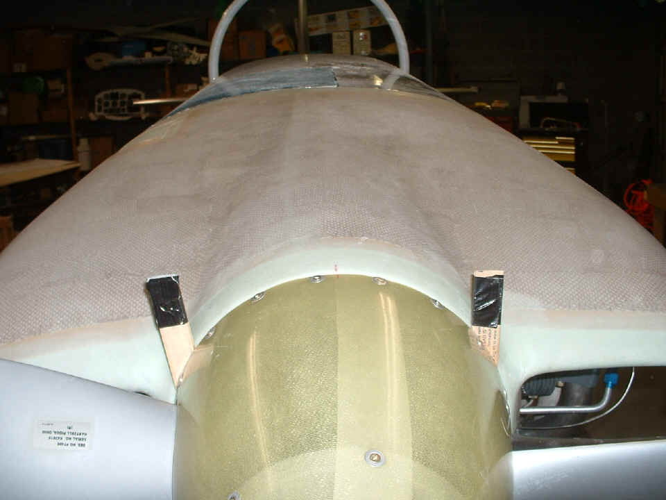
March 15, 2007: This
Thursday evening session saw the first initial fit of the upper cowl between the propeller
and the fuselage. Van's indicated that the gap between the spinner backplate and the
front of the cowl should be 1/4 of an inch. A pair of wooden paint sticks used for
stirring paint are good spacers to do the trick. With a pair of sticks secured to
both sides of the spinner backplate, we started to get the dimensions needed for a proper
fit.
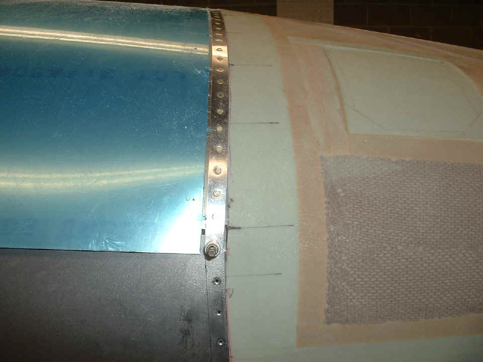
I had visited Wendell on Wednesday and Thursday evenings earlier this week to
get him started trimming the aft edge of the upper cowl to remove the overlap of the upper
fuselage skin. Here is the first photo showing a cut that allows the cowl to sit on
the aluminum plates that will eventually secure the cowl to the upper fuselage.
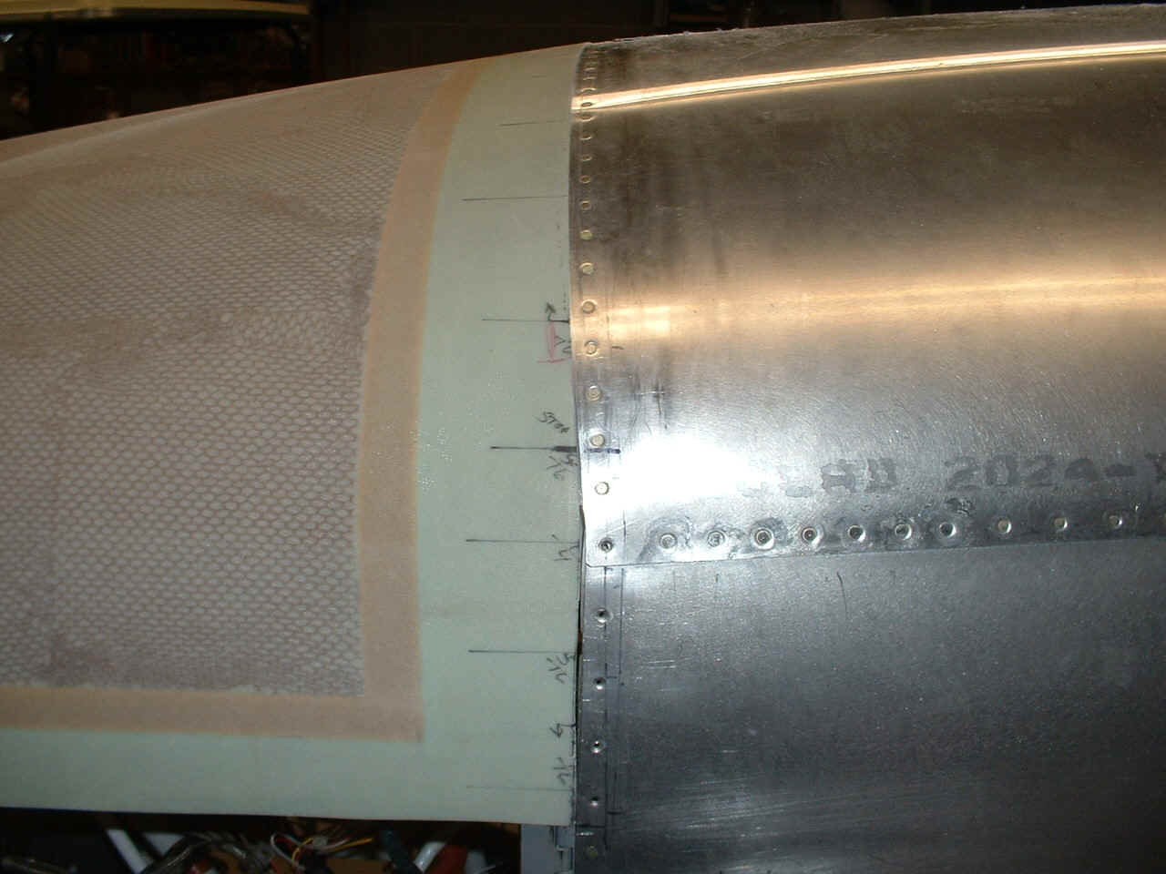
At this point in the fitting process, the adjustments to the aft edge are made
with a sanding block in very small increments. The goal here is to get a good fit
all across the aft edge of the upper cowl with the front edge of the upper fuselage skin.
The eventual gap between the fiberglass and the aluminum will be wide enough to
allow for primer and paint to be applied to the cowl and the fuselage.
| CLICK for Folks PAGE 47 | Return to Other RV Menu | Return to Main Menu Page. |