Wendell Folks RV-8 Project - Page 33.
November 24, 2006: It is the Friday after
the Thanksgiving holiday here in the USA. Wendell gets a good work session in with
me guiding his steps again as usual. Wendell will have a separate avionics master
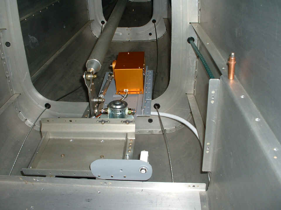
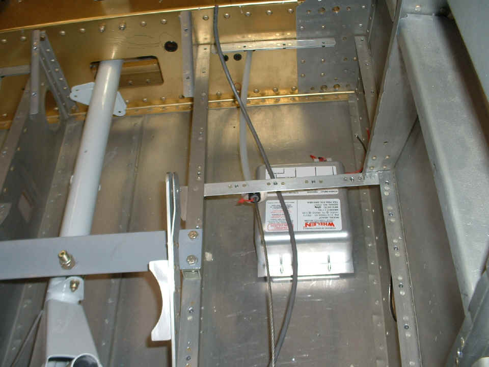
switch from the overall electrical master solenoid seen here attached to the battery
mounting tray. As a result, there has to be a circuit breaker mounted to the tray
for the wire leading to the avionics switch/breaker on the switch console up front.
This 35-ampere circuit breaker is mounted to the front of the tray allowing an access hole
through the rear baggage deck cover in case of a needed reset of the breaker. The
main baggage floor and wall plate was installed to insure the clearance of the breaker
behind the other baggage cover not shown in this photo. There is a 3/4-inch hole in
that unseen cover, directly in front of the 35-amp breaker. The breaker sits behind
the hole and would not be prevented from popping out by any baggage that could be placed
in this area.
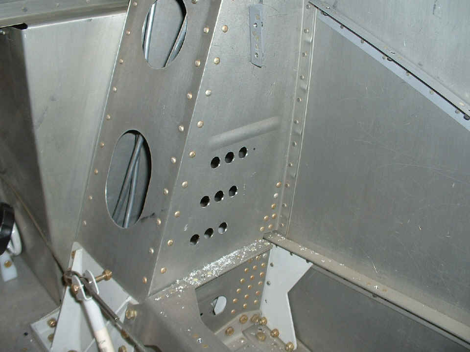
The installation of the breaker above was the next step before proceeding with
additional electrical wiring up near the switch/breaker console. Another thing that
needed to be done was the drilling of the holes for the individual avionics circuit
breakers. Since this was a process that had to happen inside the fuselage, the only
way to get the holes properly aligned was to build a circuit breaker mounting template,
drill the holes in the template correctly, then use the template on the gear leg tower
wall to accurately drill the holes as shown below. This area will be painted before
the circuit breakers are mounted.
Here is a view of the first connections to the battery area. This was one
of those times to remind Wendell about protecting the wires from chafing against the skin
of the fuselage. This conduit section is the first to be installed. The
battery ground cable is now drilled to the 3/4" aluminum angle per Van's plans.
The cables are attached to the master relay, including the damper diode and master
switch wire that will run to the instrument panel master switch itself. The black
ground wire for the servo now has a ground lug crimped on it and is secure under one of
the mounting screws.
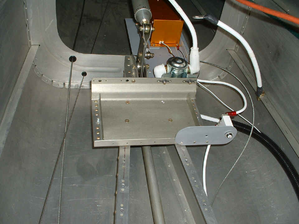
We ended the session with the connection of the avionics master power wires. I instructed Wendell to install additional corrugated conduit to protect the avionics cables from the rudder cable seen snaking around the wiring above. You may have noticed the aluminum hinge rod to the left of the battery tray running through the small black bushing in the bulkhead. It will be used for pulling the aft strobe light cable in the next work session.
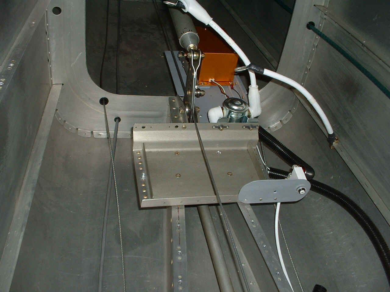
November 25, 2006: Saturday and time to get
more wiring done. Wendell added a short conduit to protect the avionics master cable
between the battery connection and the circuit breaker. This photo was taken at the
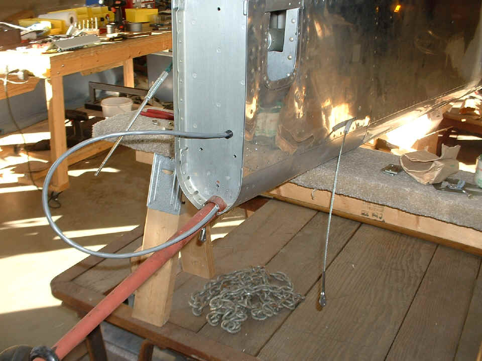
end our session and shows the aft strobe light power cable is now installed. The
horizontal stabilizer was removed before we could install the strobe cable. Wendell
told me that his young grand daughter had come out to the shop on Thanksgiving Day to see
his airplane. He asked her to try installing the nut and washer on the forward
mounting bolts of the horizontal stabilizer. Her small arm fit inside the access
hole at the rear of the turtle deck skin. She could easily install the nuts on the
four bolts. Now all we have to do is get the airplane finished and painted before
her arm grows bigger. Wendell and I cannot get our hands in there, but her whole arm
fits inside there from the outside of the airplane.
Wendell held one end of the aft strobe power cable even with the wing spar
while I cut the other end long enough to get inside the rudder bottom cap for its future
connection to the strobe light assembly there.
Speaking of the other end of the strobe cable, I realized that we could avoid
one of the issues I had to overcome here. When I drilled my power cable access holes
in this last bulkhead and the vertical stabilizer aft spar, they were already bolted
together. In this case, it was easy to put in a couple of mounting bolts with the VS
mounted temporarily to the fuselage. A pilot hole was drilled through the VS spar
and the aft bulkhead between the two steel brackets for the lower rudder rod-end bearing.
After that pilot hole was drilled, the VS was removed to allow the pilot hole to be
enlarged in both the VS and the aft bulkhead shown here. The small unibit worked
well for this process, since we did not have to drill between the steel brackets from the
outside the way I had to do on my RV-9A. The small black plastic bushing was notched
on it's front face to allow an 18-gage wire to be run through it with the 1/4" strobe
power cable. The #18 wire will power the incandescent tail light bulb inside the
strobe light assembly. This bulkhead fitting is the only place on the airplane where
a low-voltage wire will be in contact with a strobe light cable. This one-inch
passage through the aft bulkhead is not enough to induce strobe noise into the electrical
system.
Over on the work bench we see the assembled console with all switch breakers
and pull-breakers mounted. I printed a label for the console on my laser printer
earlier this morning. Not seen in this photo is the copper bus bar on the common
side of the breakers that will connect to the master relay power cable. The
alternator circuit breaker is mounted at the aft end of the console. The two
pull-breakers are for the autopilot and altitude-hold servos. There are three unseen
layers of electrical tape insulating the common bus from the side wall of the switch
console mounting plate. Wendell has also been working on his throttle assembly, but
that is part of another discussion for later.
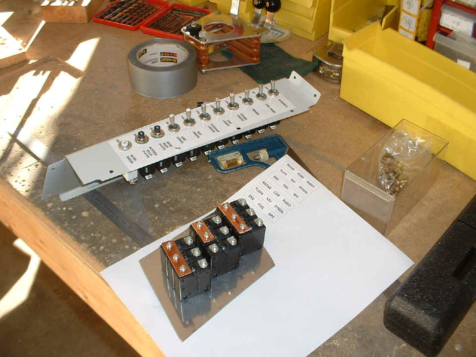
The other circuit breaker assembly in the photo above has the avionics and flap
circuit breakers mounted into the drill template used to drill the holes in the gear leg
tower shown near the top of this web page. The copper bus bar idea was used here on
all the breakers that are part of the avionics master circuit. The flap motor
circuit breaker will be wired to the master relay circuit.
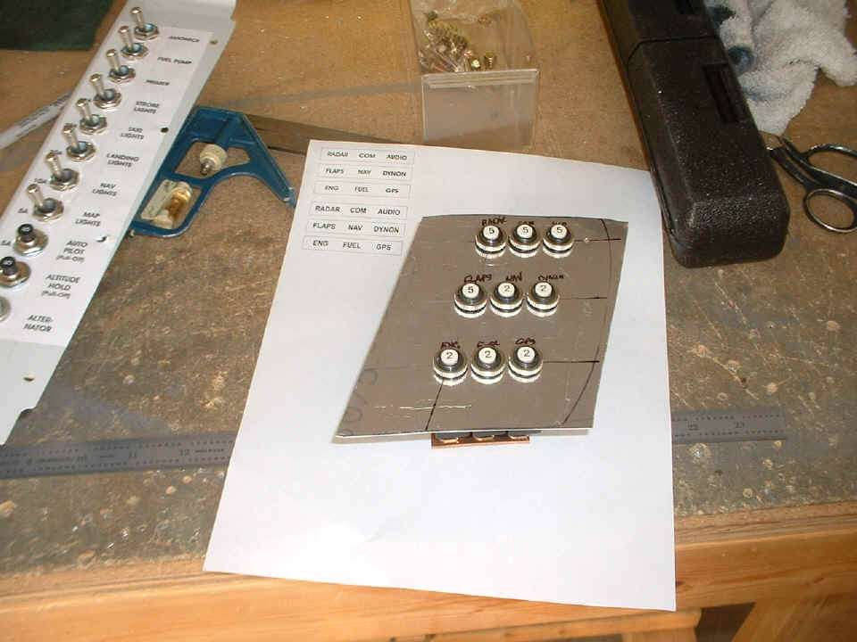
Here is a top side view of the template and the labels that will be used when
the breaker assemblies are finally mounted to the gear leg tower bulkhead plate. The
labels tell the tale for each of the protected devices. The radar transponder,
communications radio, GMA-340 audio panel, and the flap motor all get 5-ampere circuit
breakers. The remaining 2-ampere breakers will protect the navigation receiver,
Dynon D10-A, engine monitor, fuel gauges, and the Garmin GPS 396. We had one
remaining 5-amp circuit breaker left over. It will protect the Lasar ignition system
when it is finally installed. Where that ignition circuit breaker gets mounted has
yet to be determined.
| CLICK for Folks PAGE 34 | Return to Other RV Menu | Return to Main Menu Page. |