Wendell Folks RV-8 Project - Page 22.
July 12, 2006: This is an update covering
several evenings of activity with Wendell. Each day seemed to not accomplish much in
the way of milestones, but at this point, careful planning and preparations for the next
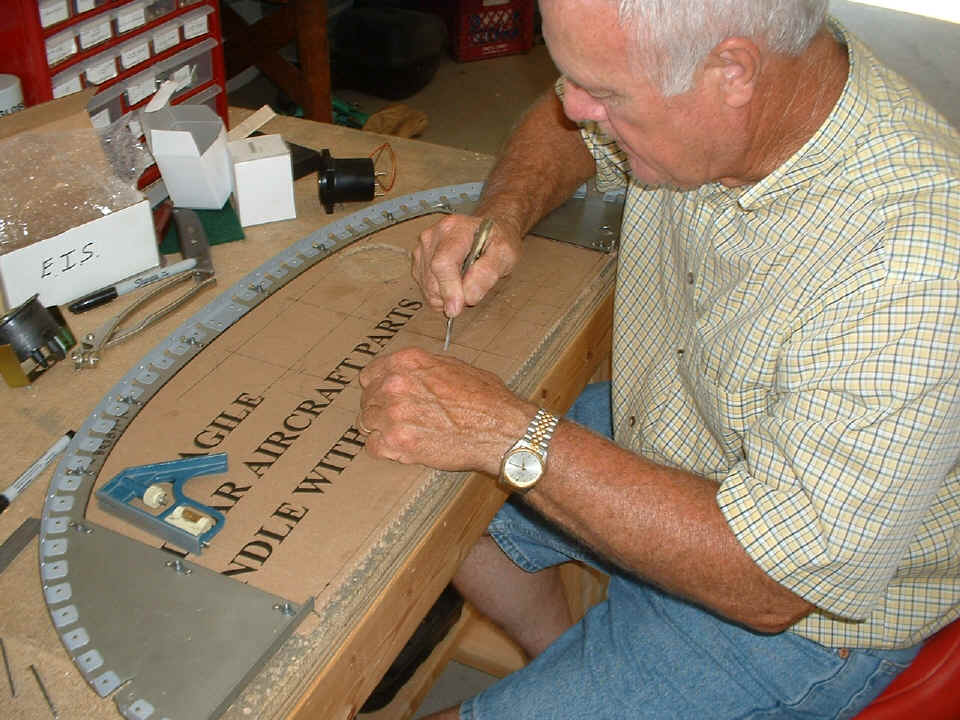
steps is a good thing. You can see below the initial layout of the instrument panel
with provisions for the short radio stack and a Garmin GPS 396 on the right side. My
old digital snapshot camera did not quite get the focus correct for this shot, but you can
see enough to see that we are headed for a nice "Six-Pack" layout.
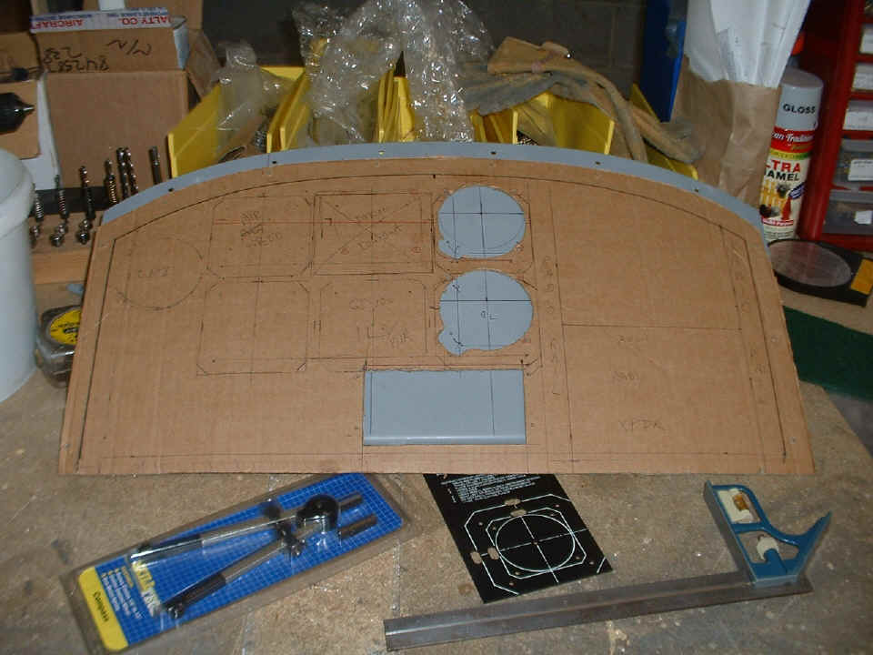
As I did before with my RV-9A panel, a cardboard cutout of the panel proved the
clearance and layout to be sure all the goodies would fit in the smaller instrument panel
of the RV-8. The rectangular cutout is the location of the GRT engine monitor.
When I had the altimeter, VSI, and the engine monitor in position on the cardboard
template, Wendell asked if we could move the two Van's analog fuel gauges up to the panel
instead of down by the fuel selector valve. I moved the engine monitor to the
"center line" below the Dynon D10-A and temporarily placed the gauges on either
side of it and found they filled in the space below the "Six-Pack" very nicely.
The passive Lift Reserve Indicator will be on the LEFT side of the main flight
instruments. There will probably be one more cardboard panel made to check the final fit
of all the instruments and warning lights before we drill the first hole in the metal
panel. Wendell had previously primed the panel, but it will be stripped and powder
coated after we finish cutting all the instrument holes and verify the installation of all
components, warning lights, etc.
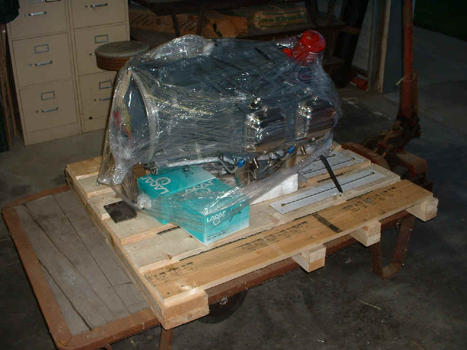
Here is the first photo taken of the new ECI O-360, 180 HP engine built by Penn
Yan Aero Service. You can see from the green boxes that the engine is equipped with
a Unison LASAR ignition at both MAG locations.
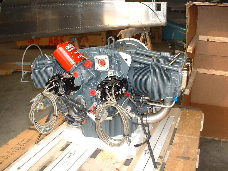
This unwrapped engine view taken the next day before sunset shows the LASAR
variable timing ignition and the control cables to both units. Since Wendell has
ordered the Dynon D10-A, there will not be a vacuum pump on the engine. When I read
the LASAR manual, I realized that we need to exchange the CHT sensor that came with the
system for a DUAL CHT probe which has two separate thermocouples in one probe. That
type of probe is available from Unison specifically for use with the LASAR system AND a
standard engine monitoring system using type "J" probes. The dual CHT
probe has FOUR wires coming from it instead of just TWO wires from a single probe.
One set of two wires will be mated to the LASAR controller and the second pair will
provide CHT information to the GRT engine monitor for that same cylinder. The
"pattern" of lines on the cylinder cooling fins is a remnant of converting this
photo from 1280 x 960 pixels down to 960 x 720 pixels to fit on this page better.
With the engine sitting in front of us, I went over all the connections with Wendell to indicate where the oil temperature probe goes, oil cooler hoses, crank case vent, oil pressure hose, primer ports, etc. I also indicated where the tachometer cable would be connected for the remote tachometer sensor providing pulses to the engine monitor.
I called tech support at Unison to verify the information about the dual CHT probe and how to exchange the single CHT probe we have now. The tech also related a story of a friend of his with the LASAR system installed on an RV-8. I wanted to be sure that where we were planning to install the unit was the best place to put it. We had already made the right decision.
A second call to Penn Yan Aero confirmed their use of the Unison T-300 timing device designed specifically for the LASAR ignition system. The engine log book had the records of the initial test run of the engine at various RPM power settings along with recorded CHT readings at each setting. That information suggested the location of the dual CHT probe which needs to be installed on the hottest cylinder. The probe placement will not be confirmed until the first test flights with the cowl and cooling baffles installed reveals the hottest cylinder head. The LASAR ignition system monitors RPM, manifold pressure, and CHT to regulate the spark timing for optimum engine performance and fuel economy.
July 16, 2006: The
usual Saturday session at Wendell's shop was all about completing the layout of the
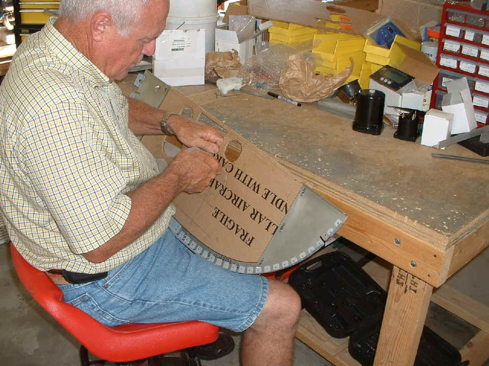
instrument panel. Another cardboard panel has revealed the issues of radio stack
clearance from the "Six Pack" of primary flight instruments. We went from
the light weight cardboard panel seen in the second photo from the top of this page, to a
second heavy cardboard panel, to the third one you see Wendell cutting out here. As
you can see, this new practice panel is from one of the Van's Aircraft empennage shipping
boxes.
The measurements from the second practice panel have been adjusted into this
third panel to insure clearance of the radio stack, while maintaining the ergonomic
spacing to adjust the altimeter adjacent to the Dynon D10-A. Wendell and I went to
the hangar to make additional measurements of my existing panel with specific interest in
the "Six Pack" and the ability to adjust things with the instruments on 4"
centers. With that bit of information established, we looked at where we could get
1/4" movement of the "Six Pack" on Wendell's smaller RV-8 panel, and get
the needed space for the proper placement of the radio stack mounting rails.
By the end of today's session, we had confirmed the locations of the four outer
gauges of the "Six Pack" along with the placement of the engine monitor and the
two fuel gauges at the bottom of the panel, centered below the "Six Pack" for a
good balanced panel. The Lift Reserve Indicator ends up on the LEFT side of the
primary flight instruments with space for the RED alarm lights below for LOW OIL PRESSURE
from the Hobb's switch that is driven by oil pressure. An identical warning light
will be next to that one that will illuminate for any alarm from the engine monitor.
The radio stack will be at the RIGHT side of the panel with the Garmin GPS 396 at
the bottom of the stack. The length of the basket for the Garmin SL-30 required the
three baskets for the GMA 340 audio panel, the SL-30 COM/NAV radio, and the GTX-330 radar
transponder to be high on the panel to clear a structural cross brace behind the panel.
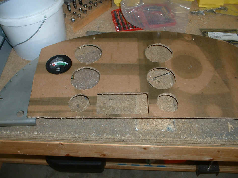
With the completion of the placement of the instruments in the cutouts above, we were able to temporarily set the radio baskets on the back of the final cardboard test panel with the aluminum mounting rails also properly placed, allowing the clearance for proper panel mounting in the fuselage. The next session should see the removal of the layout lines from the real panel and the placement of new lines based on the new measurements determined from the third cardboard panel mockup seen above.
Wendell is awaiting the delivery of his Garmin GPS 396 and the AirGizmos mounting panel. I looked at the specifications for the AirGizmos device and realized that we will have to be creative in mounting it since it is approximately 1/4" too tall to fit in our available space at the bottom of the radio stack. I have some ideas on how to fix that little dimension problem, but I want to hold the piece in my hand first before I reveal my ideas in these pages. More to come on that later.
Wendell and I both agree that the fuel tank vent lines need to be installed in the fuselage before we begin the wiring process.
July 17, 2006: Wendell received the package with the Garmin GPS 396 and the AirGizmos docking panel to put the 396 in the radio stack. It will be a tight fit, but I am sure we can get it in there with a shoe horn. I will have photos of that event when it happens. For now, I have asked Wendell to remove all the layout lines from the metal panel in preparation for implementing the final layout that was agreed upon with the cardboard mockup panel number three.
The focus of the evening session was on familiarization with the GPS 396 for Wendell. Since my 296 does much of what the 396 does, it was an easy lesson to teach. I did notice that the 396 has only ONE RS-232 serial port on it, where my 296 has TWO serial ports. I took the time to download the latest 396 software to update the unit. It came with old data in it and software version 2.8 when it arrived. The current software version for the 396 is 3.2 which corrects a few things from 2.8. I checked the manual and the PDF version from the Garmin site and found no significant changes regarding the serial port operation of the 396. I did confirm that the input to the serial port will receive data from the GTX-330 radar transponder to show nearby transponder-equipped air traffic. The serial port output can drive the Trio autopilot and the input to the SL-30 COM/NAV radio simultaneously. I will have to confirm that the output data stream format will not create any problems with the autopilot when it is configured to send VHF radio frequencies to the SL-30 radio mixed with the NMEA 0183 data stream.
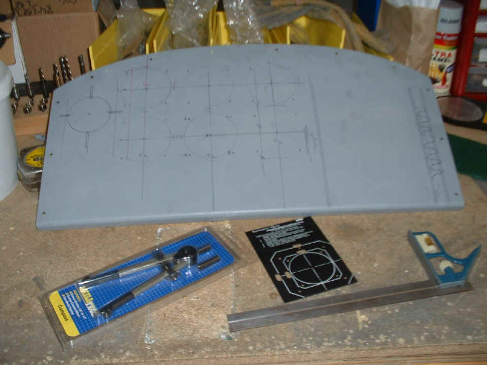
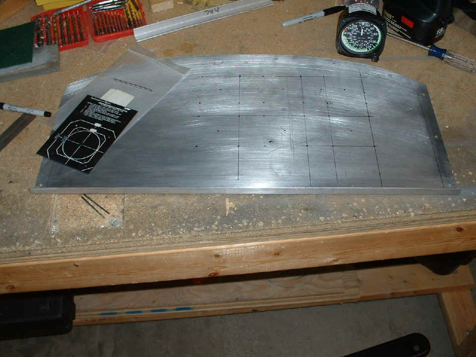
July 19, 2006: An abbreviated session tonight since we had been packing my airplane for the trip to Oshkosh that will be on Sunday, July 23rd. Notice that the primer is missing from the panel along with all the earlier layout marks. Wendell is going to get the panel painted from a nearby shop that does powder coat painting. All the primer would have been removed for that process anyway. For now, all I wanted was to get all the original layout lines off the panel to make way for what you see below.
This photo shows the beginning of the instrument layout transferred from the
third cardboard panel. We just took enough time tonight to layout the
"Six-Pack" of primary flight instruments. No holes drilled yet as you can
see. All that comes in our next evening session, along with using the circle cutter
to open up the large round cutouts for the instruments. All that is drawn on the
metal now is the center pilot hole location for each of the large instruments and their
mounting screw locations. The next step is to complete the layout and verify the
radio stack clearance from cardboard panel number three has been successfully transferred
to the real panel. After that, the drill press will get some action at last.
| CLICK for Folks PAGE 23 | Return to Other RV Menu | Return to Main Menu Page. |