Old Friends, New Adventures · · PAGE 265.
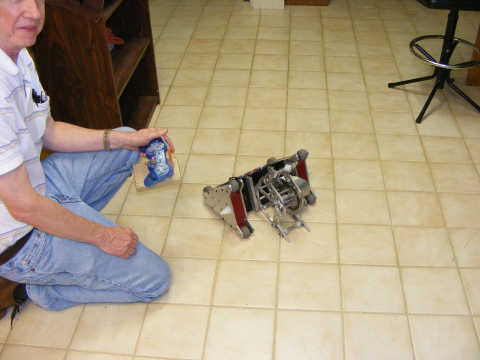
August 17, 2008: The sight-seeing
flight for Dale was completed in the morning. After lunch, I grabbed my camera and
cell phone from the airplane and we headed over to Dale's home to see his workshop and
labs. He likes to build "battle bots" as a member of the Atlanta robot
club. This one is a lightweight model named Omega Force. You can learn more
about Dale and his hobbies via his web site: http://www.wa4dsy.net.
If you look at his web site long enough, you will discover he is the guy who invented the
world's most popular telephone modems used in so many computers before we had high-speed
internet. The Hayes-compatible telephone modems of today still use his modem
control protocols.
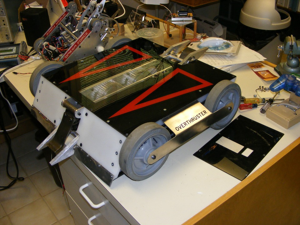
This one is in the 30-pound weight class and packs a real punch at flipping the
opposing machines off the platform arena. Dale named it the "OVERTHRUSTER"
since it can function upright or on its back. It has complete symmetry. The
controls automatically adjust to whichever side is UP at the time. It has a heavy
duty flipper at each end. By the way, when it is upright is the only time you can
see its name. This is also the side with access to the ON/OFF switch. The red
triangles point to the "business end" of this beast.
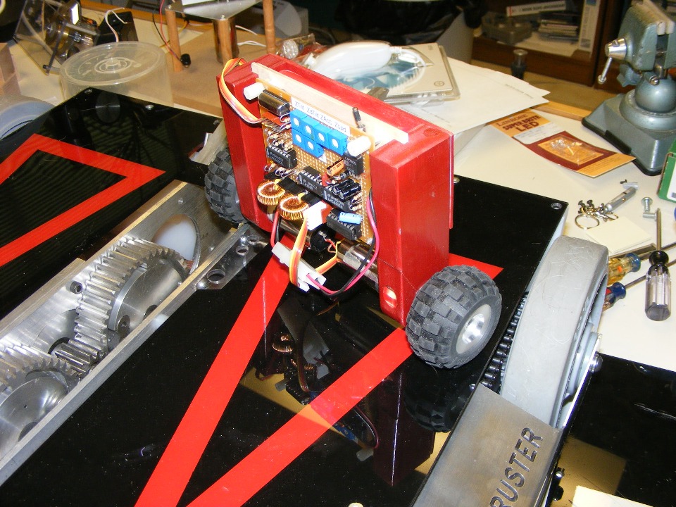
This project is a little BOT that can balance upright on two wheels. It
is all analog feedback from sensors, no microprocessors at all for this little guy.
It is a demonstrator that shows how the "Segway" people mover works. This
photo also shows the custom-built drive gears inside the bigger battle bot. Dale has
a computer controlled milling machine that can turn out those gears from raw aluminum
stock or engrave name plates. He also has a big metal lathe and wood working power
tools.
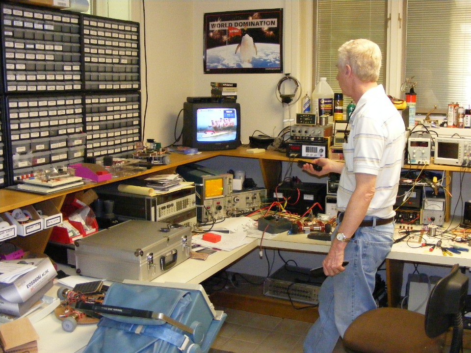
This photo gives an idea of the focal point of the lab, the RF workbench area
and electronic parts bins. If I turn around from where I am taking this picture,
there is a dark room and photo lab behind me. Everything in there has been pretty
much unused since digital camera resolution has surpassed chemical photographic films.
Now you know why all the film companies are now building digital cameras.
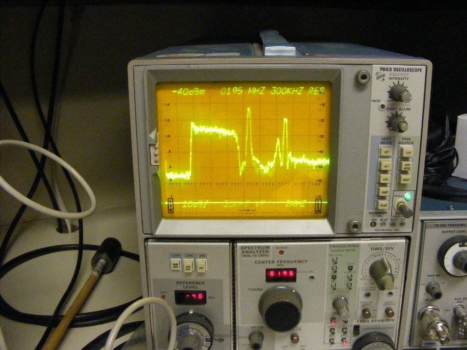
Here is a close-up of the Tektronix 7L14 spectrum
analyzer showing local analog and digital television channels in the Atlanta area.
That analog channel near the center of the screen is VHF channel 11, with an 8VSB digital
TV transmission just to the left on channel 10 (192-198 MHz). It is the broad, FLAT
looking signal with little peak at the left. The flat portion of the signal trace
from the far left of the screen going less than two squares toward the signals is the
noise floor where no television signal is present. The center frequency tuning
readout is out of calibration. There is a pot to adjust it, but I did not think to
do that before snapping these photos. That tallest analog RF carrier is at 199.25
MHz. There is a weaker digital television signal on channel 12 at the right side of
the display screen. The line at the bottom across the numbers is a retrace and does
not represent an RF signal.
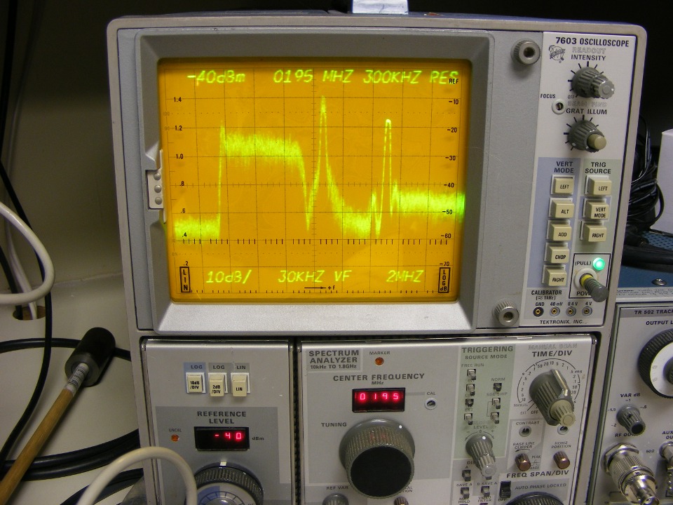
I put the scope into analog display mode to give a more realistic view of the
television signals. This is what I have been doing for the past 37 years, television
transmission systems via coaxial cable, satellite uplinks, and ground stations. I
currently work with television transmissions via fiber optics networks. For those of
you who are not familiar with the NTSC analog television signals we have been watching for
the past 50+ years, the tallest signal is the picture carrier containing the horizontal
and vertical sync pulses, plus the black and white portion of the TV channel. The
second tallest carrier is the frequency-modulated sound carrier. It is typically
transmitted at a power level from 6 to 10 dB lower than the picture carrier. It is
shown here 8 dB lower. The small signal between the two tallest RF carriers is the
color subcarrier and it varies in strength with changes in phase and amplitude with the
color content variations of the analog television picture.
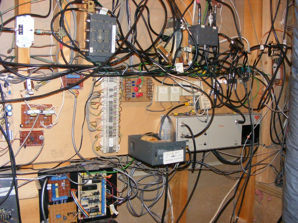
This is the electronic heart of Dale's home. These components are the
combining networks and RF amplifier to push all the VHF and UHF television signals all
over the house via coaxial cable. Telephone and intercom functions are also routed
through this closet. The open box with computer chips at the bottom center of the
photo is his weather station, which has its own television channel of course.
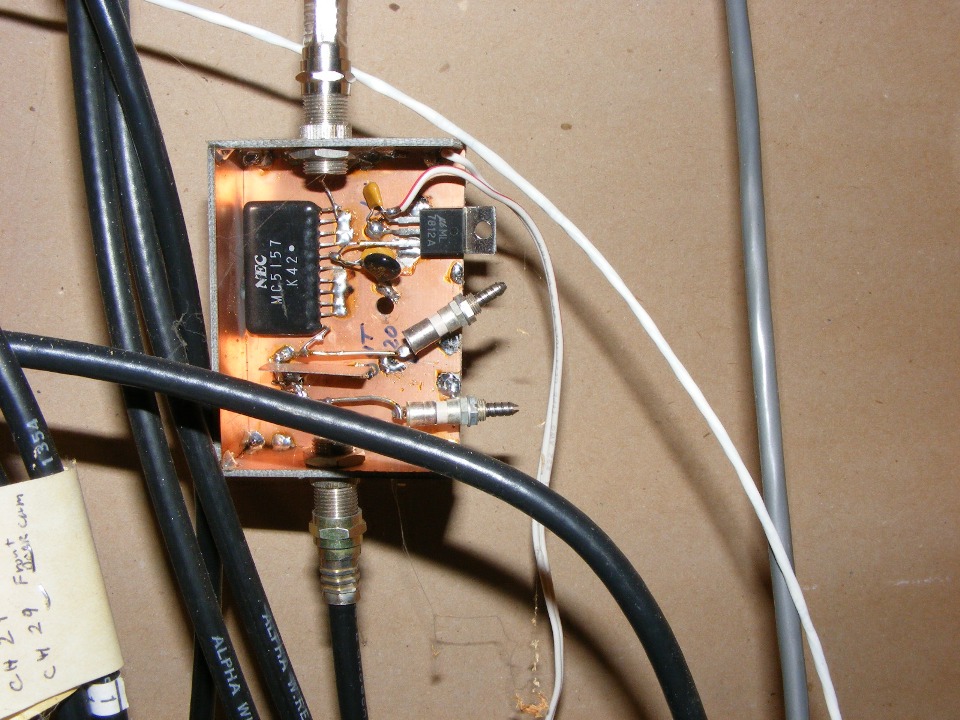
The last shot of the day is this hand-built UHF preamplifier. It has a
double-tuned RF input filter and a voltage regulator to provide 12 volts to the NEC RF
amplifier chip. The RF output is at the top of the photo. It is built on
double-sided copper circuit board material. You have probably noticed by now
that Dale builds a lot more than just robots. He does have a degree in Electrical
Engineering, the same one I have from our old alma mater, Southern Technical Institute,
Marietta, Georgia (now known as Southern Polytechnical Institute). What you have
seen here is how all electronic circuits begin life, as prototypes. When a product
has broad appeal, that is when it is designed for mass production and becomes what you buy
for your home.
August 23, 2008: It is my usual Sunday morning blog update, but with no flights of my own to report. By now you have seen that I have been editing my entries from last week for balanced page content, plus adding a few photos to the flyover page for Dale's home.
I did go over to the hangar yesterday to check on a small project Wendell was doing on his airplane during the week. You can catch up on that project and the short flight he made yesterday to give an old friend of his a ride in the RV-8. The photos and text are on Wendell's PAGE 88.
| CLICK HERE for PAGE 266 | Return to Technical Articles Menu | Return to MAIN MENU. |