FINISHING - Page 98.
February 28, 2005: Only three hours tonight,
but some good things happened after I cleaned up more plexi dust with the broom and
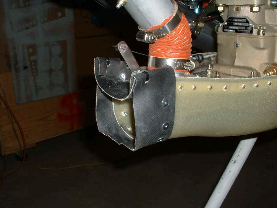
vacuum. I cut the strip of air seal fabric needed to finish the front of the
filtered air box (FAB) connection to the air inlet duct from the lower cowl. I used
the large head pop-rivets to attach the strip to the fiberglass box, then a couple of
black tie wraps to lock the two sections of air seal fabric together. The bottom
edge of the new strip needed to be cut in two places to allow the needed flexibility for
passage of the inlet duct as the cowl is put in place. Before I made the cuts, I put
the lower cowl in place and discovered it was too long on the bottom and wrinkled backward
toward the FAB. The cuts and removing some of the forward edge of the fabric at the
bottom produced a good fit when the cowl is in position.
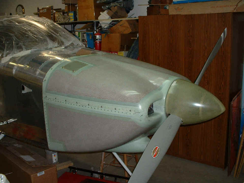
With the FAB now completed, the next thing to do is put the prop in place in
preparation for the final changes to the lower cowl if needed. It was time to clean
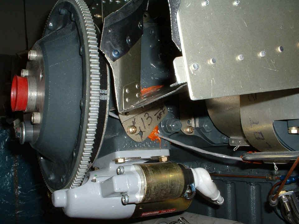
up some issues I had identified over the past few weeks. I trimmed a bit off both
sides at the front of the engine baffles where the aluminum sheets holding the air seal
fabric to the cowl interfered with the baffles. I also put the starter power
cable back on the starter motor. The gray crank sensor cable also needed some
anti-chafe treatment with some silicone tape at two places along its route past the
engine. One of those two locations is almost completely hidden behind the cylinder
head oil drain tube in the lower right corner of this photo.
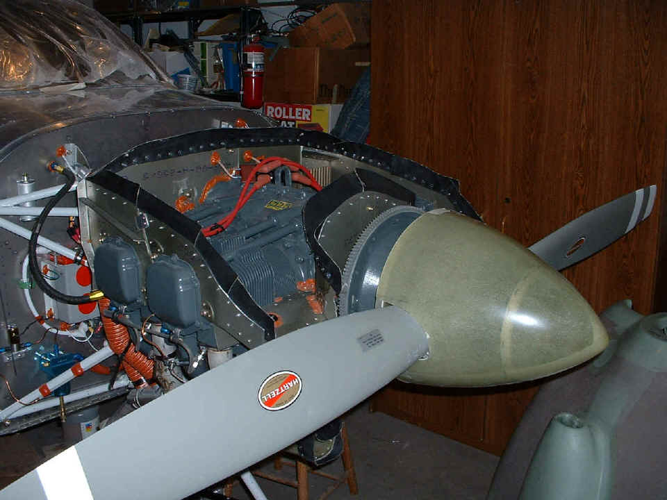
When the prop was installed, I tightened up the alternator in its proper
position and started to work on the fiberglass spinner.
Here is the result of the preliminary fit of the spinner on the prop.
That handy piece of masking tape helps out when you need it. I will need to twist
the propeller blades by hand to determine how much more fiberglass must be removed from
the spinner to clear the prop pitch angle changes. For that I will need the help of
a local RV-8 builder I know. He has been wanting to come see the airplane, and now
is the time I need him for a few minutes of assistance. I will have to give him a
call if he does not see this before I can call him.
I ordered a few items from Spruce today for doing fiberglass work and to be sure I have some strong stainless steel 6-32 screws on hand for those access panels at the front and the two at the rear of the airplane, along with some for the radio baskets in the stack.
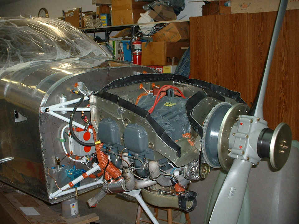
March 1, 2005: A new
month begins with a milestone moment. This is the first fitting of the cowl and
engine since I put on all the engine cooling baffles. I found one baffle location at
the front RIGHT side of the propeller that still needs a bit of trimming to ease the cowl
installation. I also had to extend the nose gear leg notch on the lower cowl about
another half an inch toward the nose.
There is a bit of symbolic history in this photo that I noticed. In the
upper right corner of the photo is an old SIG Kadet radio-controlled model airplane box.
That was my first home-built airplane back in the winter of 1977-78 when I lived in
Kissimmee, Florida. Now this project is one that I can really enjoy and share with
others.
"It's been a long road, getting from there to
here."
"It's been a long time, but my time is finally near."
"And I will see my dream come alive at last. I will touch the sky."
"And they're not gonna hold me down no more, not they're not gonna change my
mind."
(Enterprise theme written by Dianne Warren, performed by Russell Watson.) You can see all the lyrics and hear the music on this page.
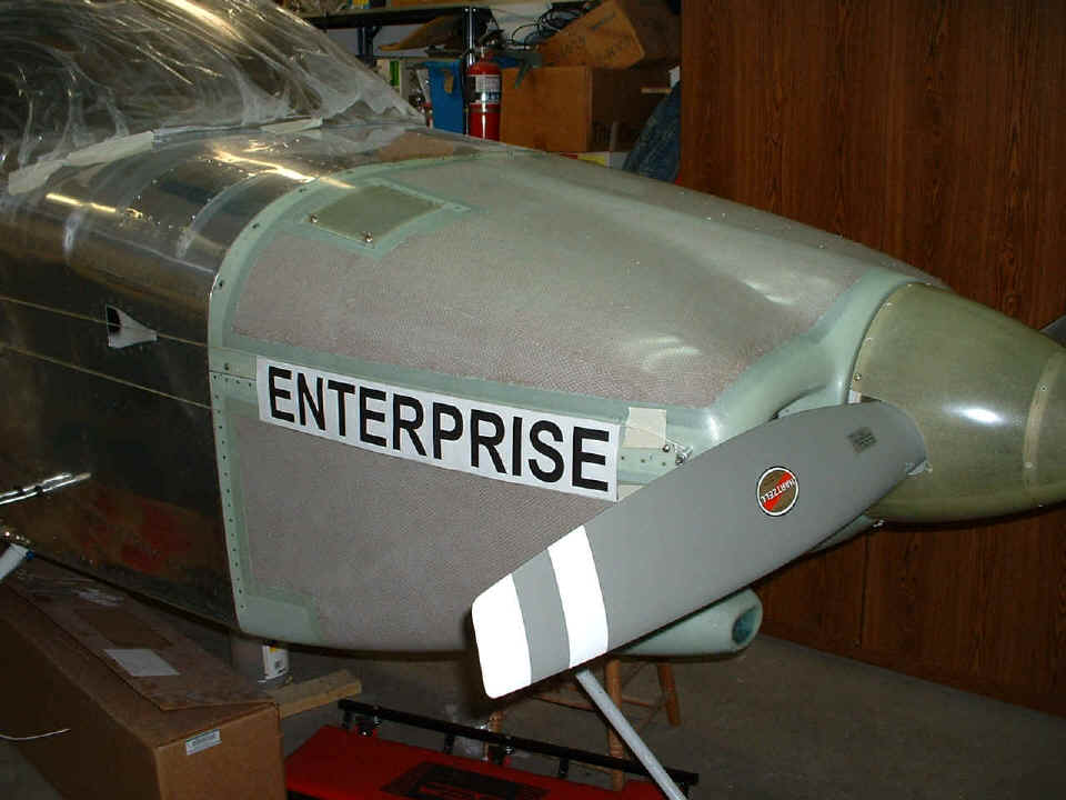
The last shot of the evening shows the first experiment with 3-inch letters for
the aircraft name. I will try different sizes as needed to get the placement of the
retaining screws to fall in appropriate places, etc. The two strings are about 3.5
inches apart on the cowl and represent the top and bottom limits of the central stripe
down the side of the fuselage. They come together approximately one inch apart near
the tail. The black letters from my laser printer will actually be white on the
airplane. And the spinner cone and the two spinner bulkheads have been match drilled
for #8 screws. In the next session, the platenuts get installed on the bulkheads.
I managed to twist the prop blades by hand to determine the maximum amount of the
cone to remove for prop clearance with pitch changes in flight.
March 2, 2005: A good
day for working on the airplane in between responding to some emails and phone calls about
my prospects for employment. Let's talk about the airplane. Today it was work
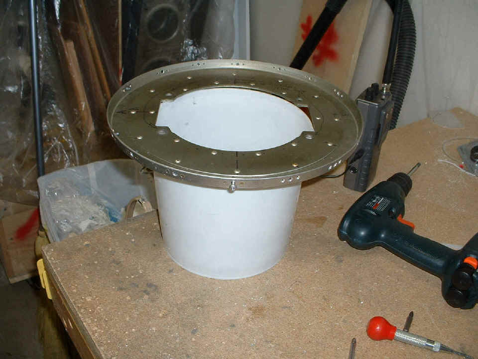
on the spinner bulkheads and the fiberglass cone. You can see in the photo above
that I finished last night with the holes match-drilled through the fiberglass cone into
the two spinner bulkheads. I had to remove the propeller and both bulkheads to
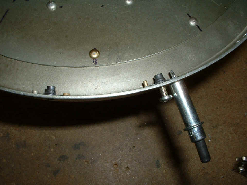
install the #8 platenuts for the mounting screws. In the photo below, the spinner
back plate bulkhead is drilled and countersinked at the rivet locations that hold the
platenuts in place.
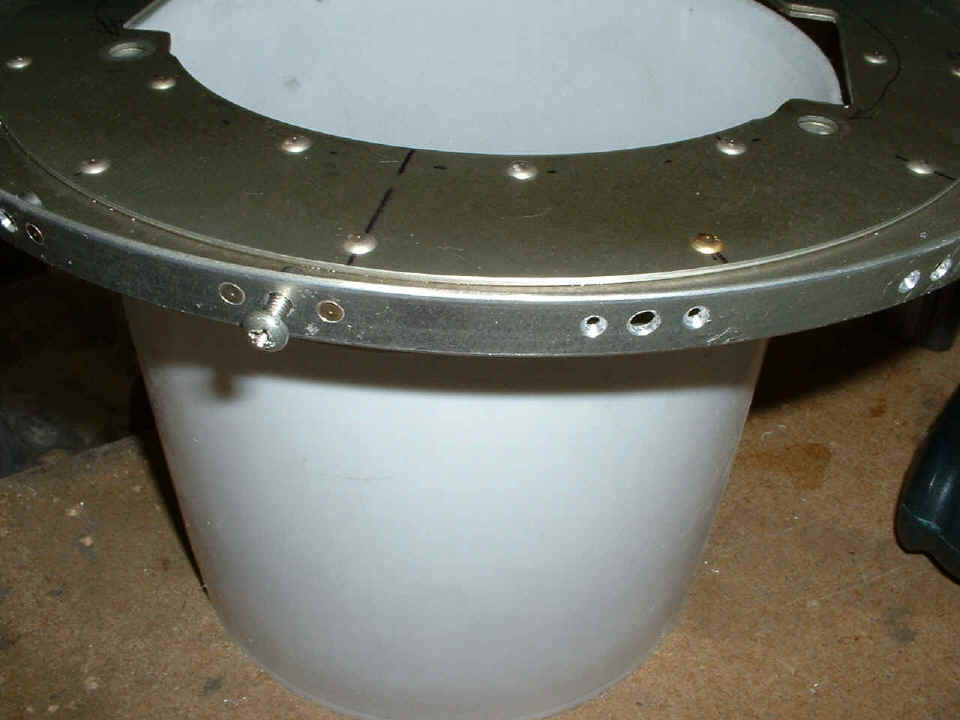
This close up shot should give some idea of the preparations for the platenut
installation. The center hole in each group of three holes was match-drilled when
the fiberglass spinner cone was on the prop bulkheads.
This one shows the platenut ready to be riveted in place using my rivet
squeezer. The platenut on the left is finished, while the one on the right is held
in place by the cleco, using the screw and the other rivet for alignment. What was
not shown is the step of drilling the two rivet holes adjacent to the screw hole.
For that step, the screw is threaded part way into the platenut, a clamp is put onto one
side of the platenut when it is aligned parallel to the edge of the spinner back
plate. A center punch through the rivet hole in the platenut insures the #40 drill
will find its mark without wandering around and mis-aligning the platenut from the
parallel path.
When the first hole is drilled, the cleco goes in, the clamp is
removed from the other side of the platenut, the screw stays in, and the #40 drill goes
through the other side of the platenut from the center of the back plate toward the
outside.
Since I have TEN pictures on this page, you will have to go to PAGE 99 to find
out how this ends.
| CLICK HERE for Finishing Page 99. | RETURN to MAIN MENU. |