FINISHING - Page 92.
February 10, 2005: Looking closer inside the
carb air inlet with the camera in macro mode, we can see the carburetor and air filter are
NOT in the center of the fiberglass structure. The cowl is centered on the propeller
spinner back plate. Everything else is secondary to that aerodynamic requirement.
The location of the carb and the alignment of the filtered air box (FAB) are the
first issues that have to adjust to that reality.
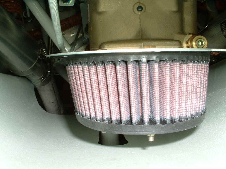
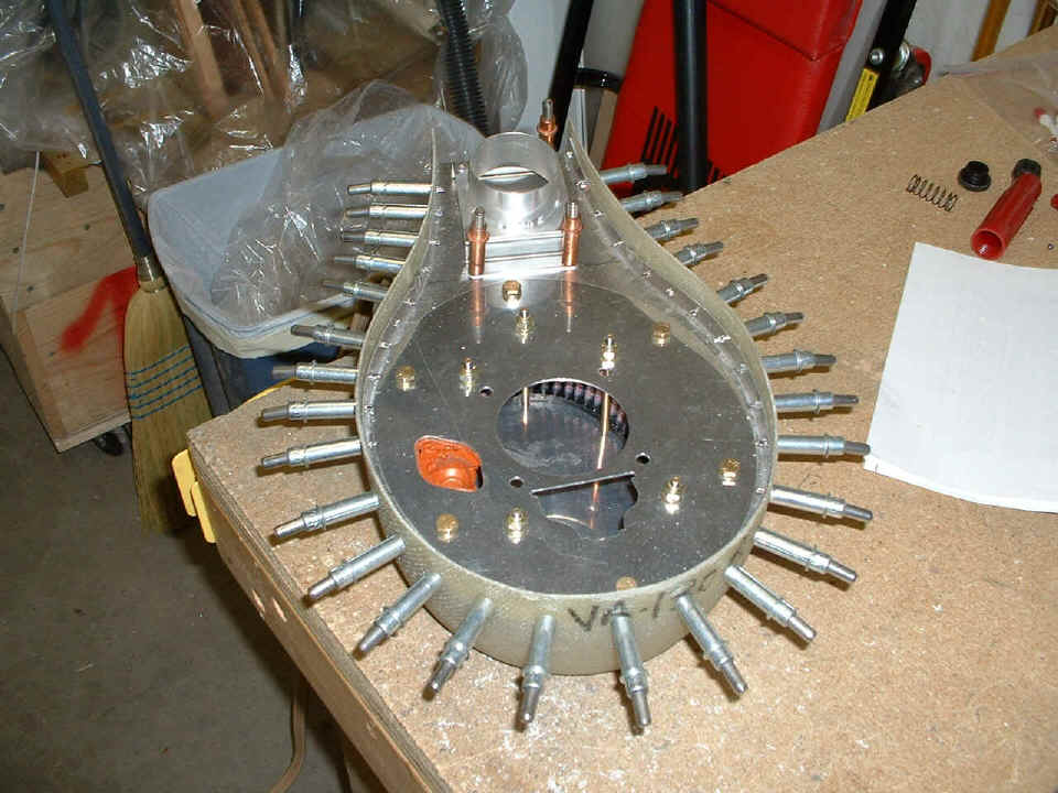
In the picture above, we can see the offset of the carb in two ways. The
first is the location of the nose wheel gear leg and the notch in the cowling below the
air filter and the carburetor. The second way is the camera angle. I put the
lens into and near the center of the carb air inlet seen in the last picture on page 91.
Look at the hex-head bolt that is just visible above the aluminum plate atop the
air filter. See the casting seam at the center of the carb above it? The head
of that bolt is directly in front of the seam on the carb casting. Now you have an
idea of just how much I have to skew the forward opening of the filtered air box toward
the camera location and the center of the air inlet on the lower cowl.
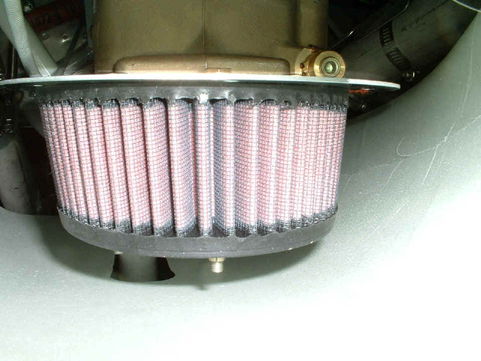
In this second picture, I wanted to show that the air filter is closer to the
cowl on the right side of the photo than on the left side. I put a paint stirring
stick in there to get an idea just how much clearance there is between the air filter and
the cowl. I have estimated about 3/4 of an inch. It gives me an idea of how I
am going to have to align and modify the fiberglass filtered air box that will surround
the air filter element itself. The instructions used the term "biased to the
RIGHT" which is the LEFT side of this photo. I could also end up cutting off
the excess threads on the bolts that hold the filter assembly together since I may need
the bottom of the FAB to sit a bit close to the filter element itself. What is all this about? The size and shape of the FAB helps
to provide the correct manifold pressure and therefore power from the engine in an
efficient range of throttle and mixture settings for a given propeller pitch
setting. It's all about performance!
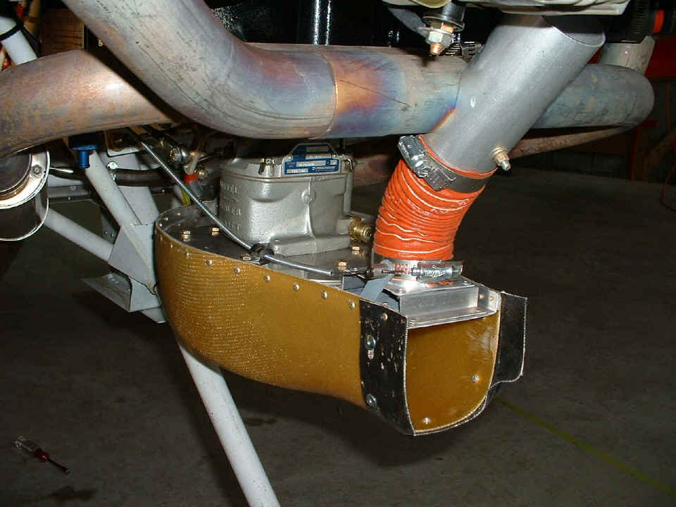
Here is the picture I took of David Edgemon's FAB on the bottom of his engine.
Now my job is to build my FAB with the correct alignment, length, and height to fit
in the space depicted in the two photos above this one! And of course, I also have
to connect the carb heat plumbing you see in the photo below. Now you have an idea
of what to look for in the coming sessions. Are we having fun yet?
The total construction time on the airframe is 1618.5
hours! Building this airplane sure makes up for not having an Erector Set when I was
a child. The kid in me is enjoying this project to the MAX!!!
February 11, 2005: A short
session of 1.2 hours, typical for Friday nights. I took this photo to show
something that is seen in the two filter photos up at the top of this page. The
filter is held in place by long bolts going from the mounting plate to the carburetor down
to a bottom plate under the filter. The bolts are skewed at an angle, not
perpendicular to the plates - this is by design and mentioned in the instructions.
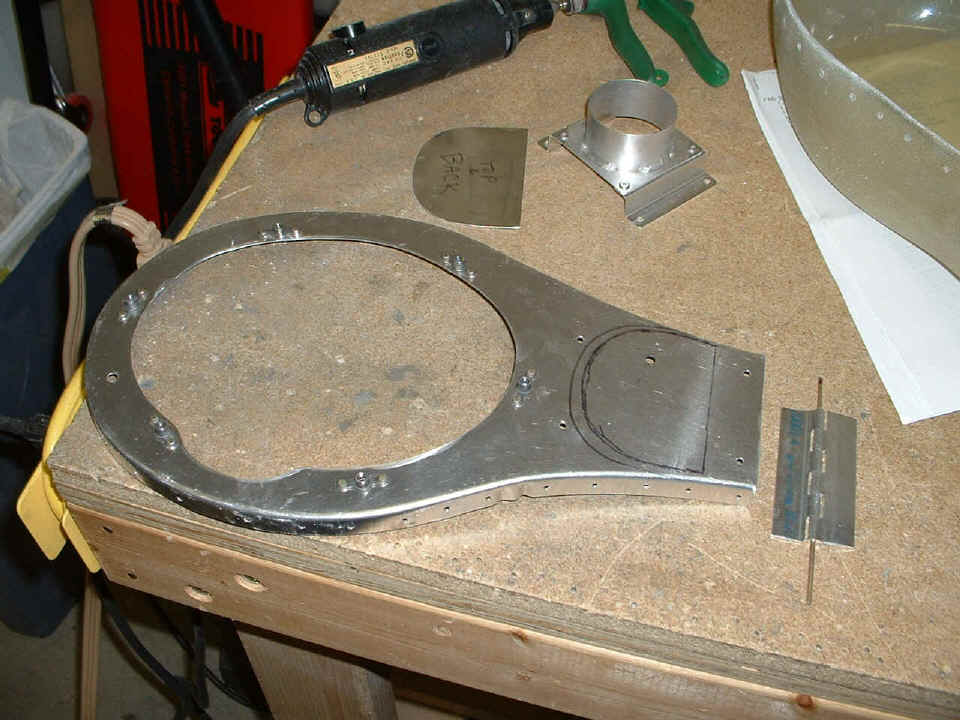
The thing that shows up in the photo below is that the oval cutout in the VA-130B plate
below is the size of the bottom of the filter, not the top. This will require me to
enlarge that oval-shaped hole to finish the assembly. You can see where I have drawn
a center line on the VA-130B, but you cannot see the line I drew on the mounting plate
that holds the filter. That part of the filter is turned down against the garage
floor in this photo.
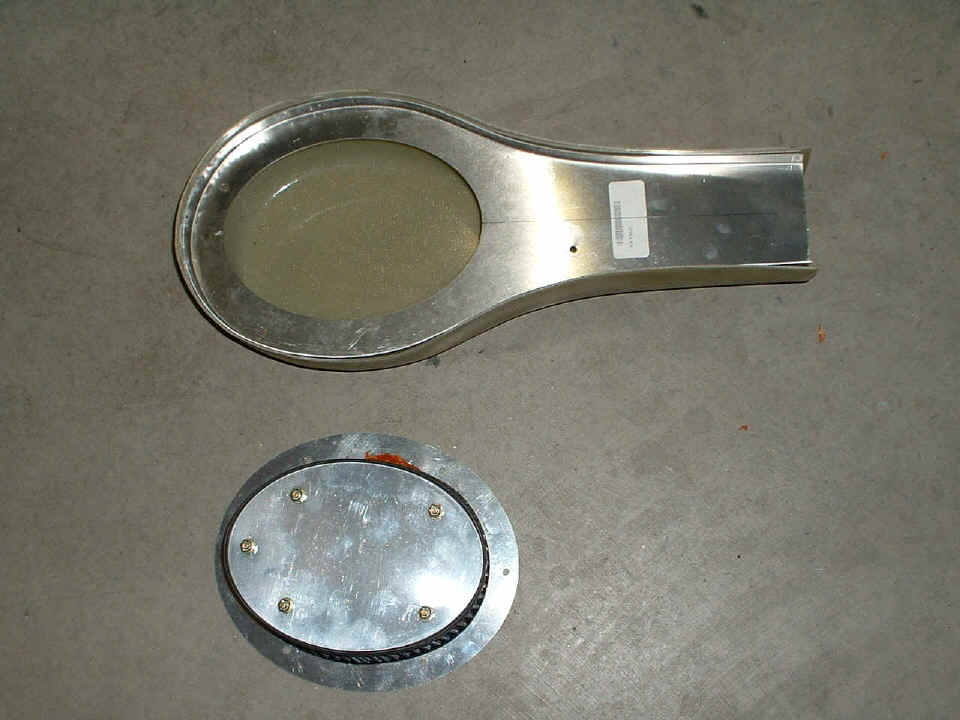
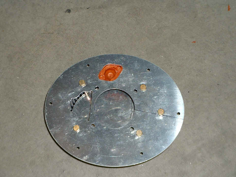
Here is the mounting plate side of the filter assembly showing the "skew
line" that was identified in the text above the second picture at the top of this
page. That line will be oriented parallel to the line on the VA-130B when the two
pieces are mated and secured. The RED RTV did not come out as good as I hoped, and
will be revisited in another casting.
Since the filter was bolted on the carburetor last night inside the cowling,
you can tell I had to take the cowling off the airplane to get the filter assembly out.
The weather is looking good for tomorrow and a visit from David Edgemon is planned
when he flies his RV-9A over to Dallas Bay Skypark for lunch and a visit to my shop.
This will be his first time to see my work and a chance to ask him some "hands
on" questions about the parts of the airplanes that are similar. He built a
tip-up canopy, and mine is a slider of course! And we are going flying in his
airplane after lunch, so come back tomorrow night for pictures and descriptions about that
part of the visit.
February 12, 2005:
Saturday! David Edgemon came over in his RV-9A and we went flying. I was busy
holding the stick and did not take any pictures in the air, but there are a few of David
and the airplane on the ground at Dallas Bay Skypark. CLICK
HERE to see those pix. We also came to my shop to let David see the differences
from his tip-up canopy RV-9A and my sliding canopy RV-9A.
February 13, 2005: I put in a good day today
to make up for having some fun yesterday and NOT working on the airplane project. It
was all about the filtered air box and fitting it to the cowl, etc. I took off the
forward top skin to show David the innards of my airplane between the firewall and the
instrument panel, since that is part of the big difference in the two airplanes.
Today, I had to put that skin back in place in order to fit the cowl properly and verify
clearance of the filtered air box from the lower cowl. Sorry, no macro pictures
today since it was all out of focus (way too close to the lens). Here are the
basics. I enlarged the oval cutout on the top plate to clear the filter assembly as
needed.
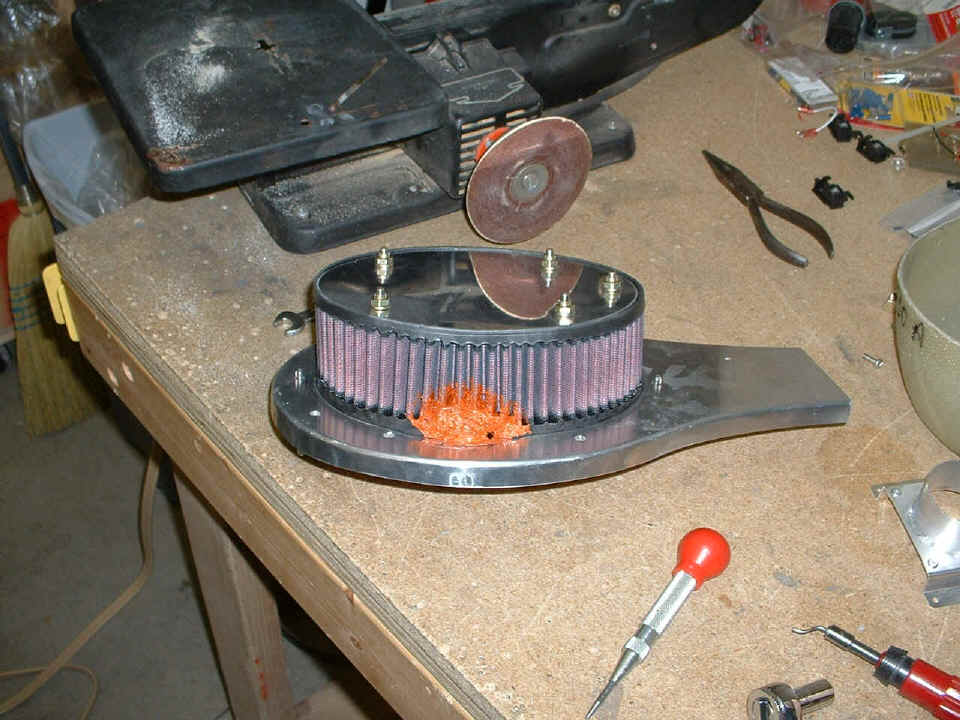
While the cowl was in place, I made sure the alignment was correct for the top
plate and marked it for drilling. The photo above shows the results of the
match-drilled holes in the VA-130-B top plate to the filter mounting plate. The
photo below shows the top side of the assembly.
I also added the 10-32 platenuts to the VA-130-B before putting the assembly
back on the carb and fitting the cowl again. The photo below is after all that
fitting was completed and I have confirmed that the depth of the fiberglass box relative to
the filter assembly inside it is correct to clear the lower cowling. As you can see,
I have drilled and clecoed the box and the mounting plate together, but have not yet
removed the excess fiberglass above the VA-130B plate.
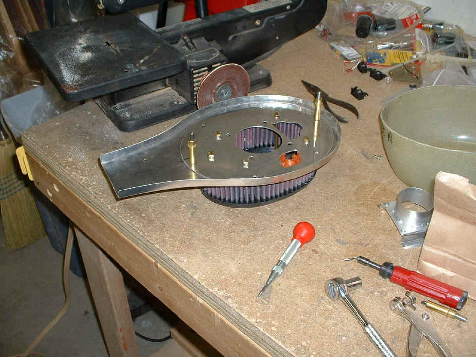
The last picture of the day is the way things will remain while I take a short
business trip for a few days. The VA-130-B plate also needed to be fluted to raise
the front edge of it to line up with the upper edge of the air intake port on the lower
cowl. I have cut out the carb heat door to fit the throat of the FAB and done a
quick layout of the location for the door and cut the hinge to proper size. The
fiberglass box is cut and sanded to the proper depth. Riveting won't be done until I
finish the carb heat door installation.