FINISHING - Page 91.
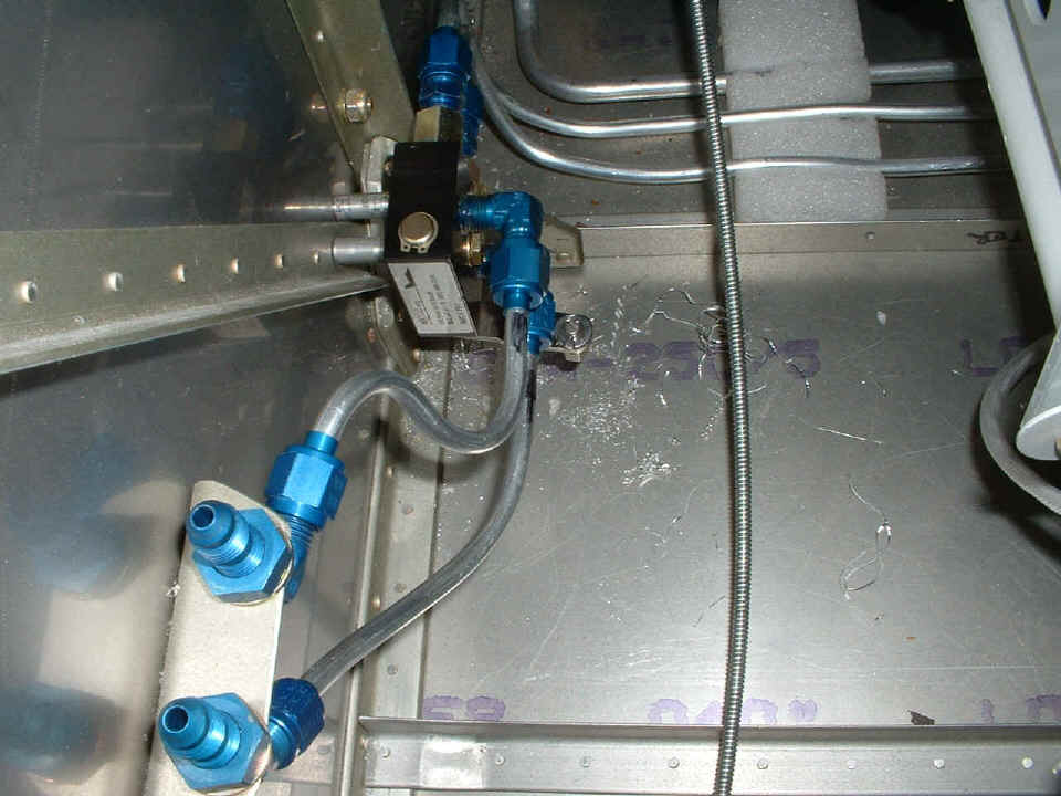
February 8, 2005: The Matco parking brake
valve needs a pair of right-angle AN fittings which I ordered today and will be delivered
tomorrow. (I sure love being in the "local" area for UPS ground deliveries
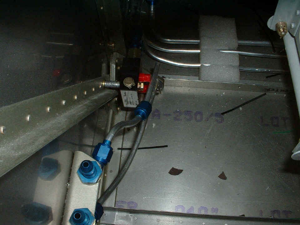
from the Atlanta area.) Here is the initial fit of the valve using a long AN3-22
bolt and a spacer I made. The hole in the firewall had been drilled earlier to mount
a bracket for the fuel flow sensor on the outside of the firewall. I used my Dremel
cutoff wheel to cut both brake lines to fit to the AN tubing fittings on the valve.
I left the two red plugs in the valve that will be replaced with AN822-4D elbow fittings
tomorrow night. These two cutoff tubes will be fitted to them at that time.
Those two blue fittings pointing toward the camera will get the black flexible hoses
reconnected after I finish up this valve work. I had to pull the bolts holding the
rudder bars on the LEFT side and CENTER brace locations to push the rudder pedals aft and
out of the way.
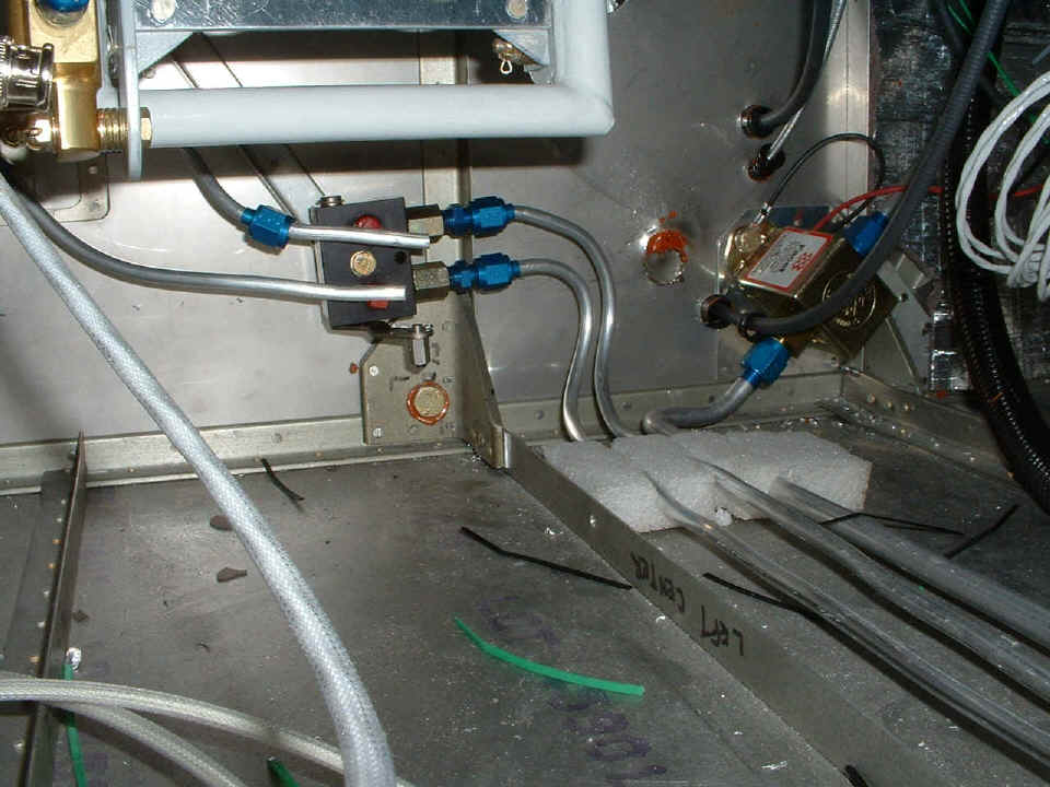
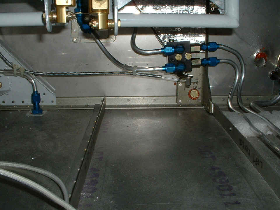
Here is the first look at the valve from the wing spar area. I will
finish the horizontal alignment of the valve and the aluminum tubing when I get the other
two fittings installed. I may put in a second bolt and spacer to further secure the
valve. I have looked at other builder sites where they had put a parking brake valve
in during initial assembly. Since the parking brake is an "after thought"
for me, I thought this location would be the least difficult method to install the valve.
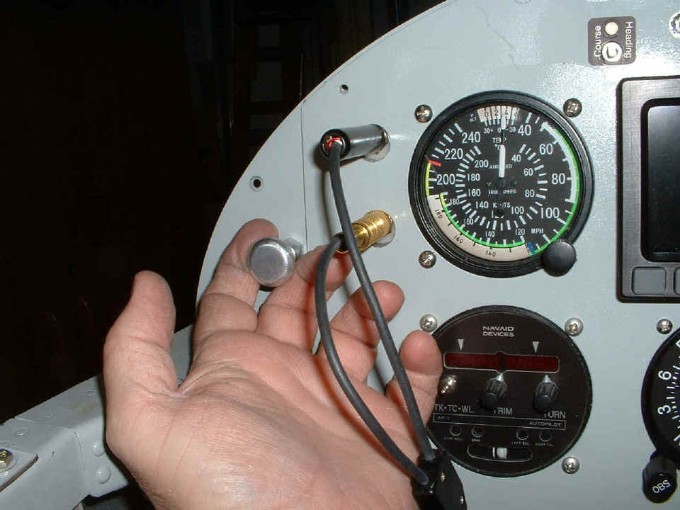
And of course, the valve needs a control knob and here it is. The
instrument panel was put in temporarily to determine if I could enlarge an existing hole I
had already drilled in the permanent portion of the panel. I used my small Unibit to
enlarge the hole and move its center away from the main panel edge at the same time.
The hole was 1/4", now it is 3/8" in diameter. I wanted to sit in
my seat location to be sure the knob would be easy to operate in that corner of the
cockpit. I had considered putting the knob in the blank panel at the top of the
radio stack, but that would immobilize that panel for the future. It would have made
the knob accessible to the copilot position, but I considered that to be a secondary
issue.
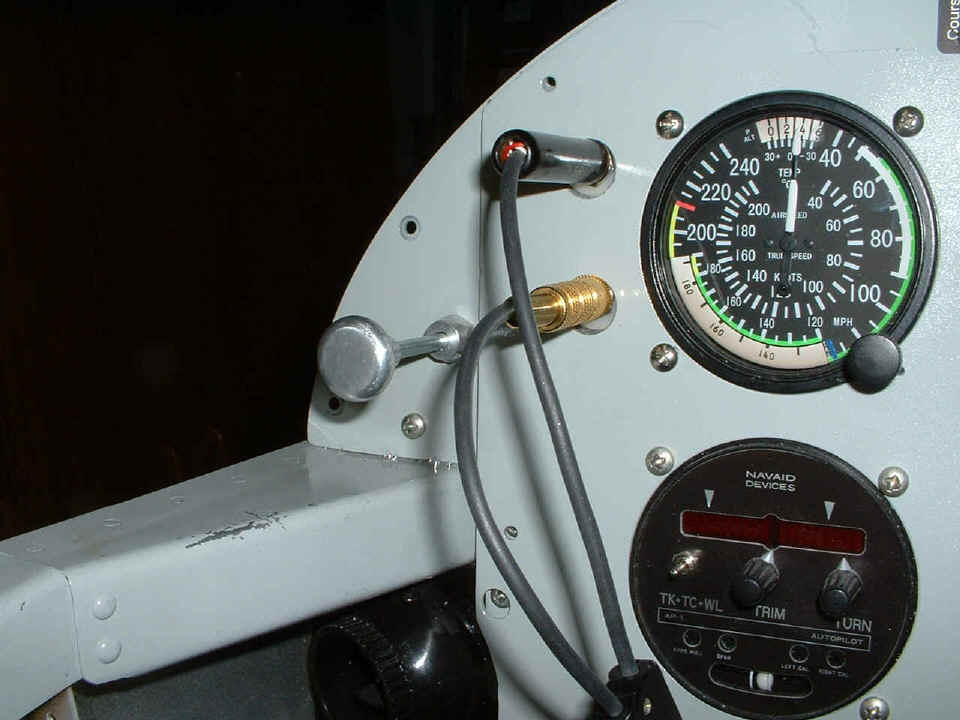
This shows the cable in the "locked" position that it should have
when it is finally connected to the parking brake valve. I bought the matching round
stick-on label for the knob, but will not put it on until later. I can see that I am
going to need to do some clean up and spray painting soon.
I talked with David Edgemon this evening for a few tips on the carb air filter assembly. With the weather looking good for Saturday, he may fly over to Collegedale Airport for a visit. He wants to see my fuel flow sensor installation and he offered to let me get some stick time in his airplane. Lunch will be on me of course! I will post some pictures if the weather stays good and he gets here.
February 9, 2005: A short session tonight to
install the AN822-4D elbow fittings on the parking brake valve assembly. I also cut
the remaining brake lines to the correct length and drilled a second bolt hole through the
firewall and the aluminum angle on the front side of the firewall that is the mount for
the fuel flow sensor. The new fittings are clearly visible along with the black ink
I put on the aluminum tubing to remind me which end is which on those short tubes. I
had to make one of those aluminum spacers about 0.060" longer than the other since
only one of the long bolts passes through the aluminum angle entering the left side of the
photo. What you don't see is the aluminum angle that is on the other side of the
stainless steel firewall at that location as the other strength member securing the valve
with those two bolts. The control cable is not yet connected to the arm of the valve
in this shot.
Here is the result after vacuuming the area and connecting the control cable
and securing it along its path from the control panel knob to the valve actuator arm and
B-nut setscrew assembly. I used 1/4" clear plastic tubing on the lines where
the tie wraps secure the cable along its path. The control cable was binding a bit
until I put the last tie wrap and clear plastic tubing on the lower brake line nearest to
the valve. Since the actuator arm is so far from the firewall, it is not easy to put
a traditional cable clamp here to do the job of securing the sheath of the control cable.
There is nothing currently on order from Van's or Spruce at this time. The next session will find me working with the insulation blanket now that I am finished mounting stuff to the firewall and drilling holes through it (I hope!). I will be getting the cowling out again to measure the distance from the carburetor to the air inlet scoop. That will get me back on the filtered air box part of the project.
February 10, 2005: Add 3.5 hours to the log
book tonight working on the fit of the last large piece of the firewall insulation blanket
around the brake lines on the left side. I also cut the two small rectangles of
blanket that go on the upper center panels of the firewall. The last wire entry port
through the firewall was also sealed with the RED RTV near the tachometer sensor.
Nothing new there to really photograph, but this photo gives an idea of what it is going
to look like when it is time to rivet on the top skin. Since part of the assembly of
the filtered air box requires the upper and lower cowl to be on the airplane, I had to put
the top skin on in order to properly align the cowling. I am having images of
bucking rivets already.
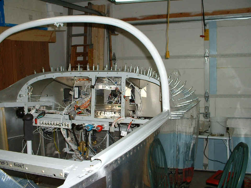
Before I clecoed the skin in place, I put the two mounting angles between the
firewall and the F-7105 instrument sub-panel. Those are the angles I made to hold
the mounting plate for the solid-state ignition module and the altitude encoder. I
left the plate out since I want everything to be in the final condition that it will be
when I am ready to rivet that skin in place. Let's call this a dress rehearsal for
that day.
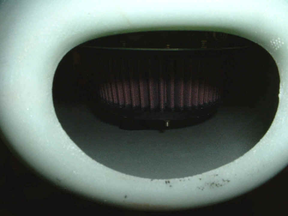
Now, let's get to what this is all about, building the
filtered air box. Here is how the carburetor ram air scoop appears on the
cowl as it comes from the factory. In the coming sessions, I have to fabricate an
aerodynamic fiberglass inlet connected to the inside of this opening for smooth air flow
into the filtered air box. The whole purpose of putting the cowling on was to get a
measurement from the air intake to the aluminum air filter mounting plate that you can see
above the air filter element itself. In my case, the distance from the FRONT of this
air intake to the forward edge of that mounting plate that bolts to the carburetor and
holds the filter is approximately 6.25 inches.
Let's GO TO Page 92 to get a closer look at the problem of building a filtered air box.
| CLICK HERE for Finishing Page 92. | RETURN to MAIN MENU. |