FUSELAGE CONSTRUCTION - Page 36.
January 6, 2004: I managed to work on the
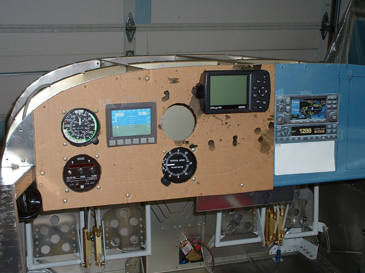
cardboard instrument panel tonight. It opened my eyes to some practical matters.
I also printed a cutout template for the Grand Rapids engine monitoring system to
see where that will fit into the scheme of things. As you can see below, the Navaid
Devices wing leveler has taken its place with about 1/4" of clearance at the back
from the forward canopy deck. The airspeed indicator is in its proper position
with
no problems. The vertical speed gauge is fine, and of course the altimeter is off to
Van's to be exchanged for one that is calibrated in INCHES, not millibars. I like that position of the Garmin 196. Now, you say, what do
you need the 196 for if there is going to be a Garmin 430 in the stack. Considering
the cost of the 430, it may be a while before it gets there. That big white space in
the stack is for Grand Rapids Technology Engine Information System 4000 engine monitor. It could also fit to the right of the
vertical speed indicator if necessary.
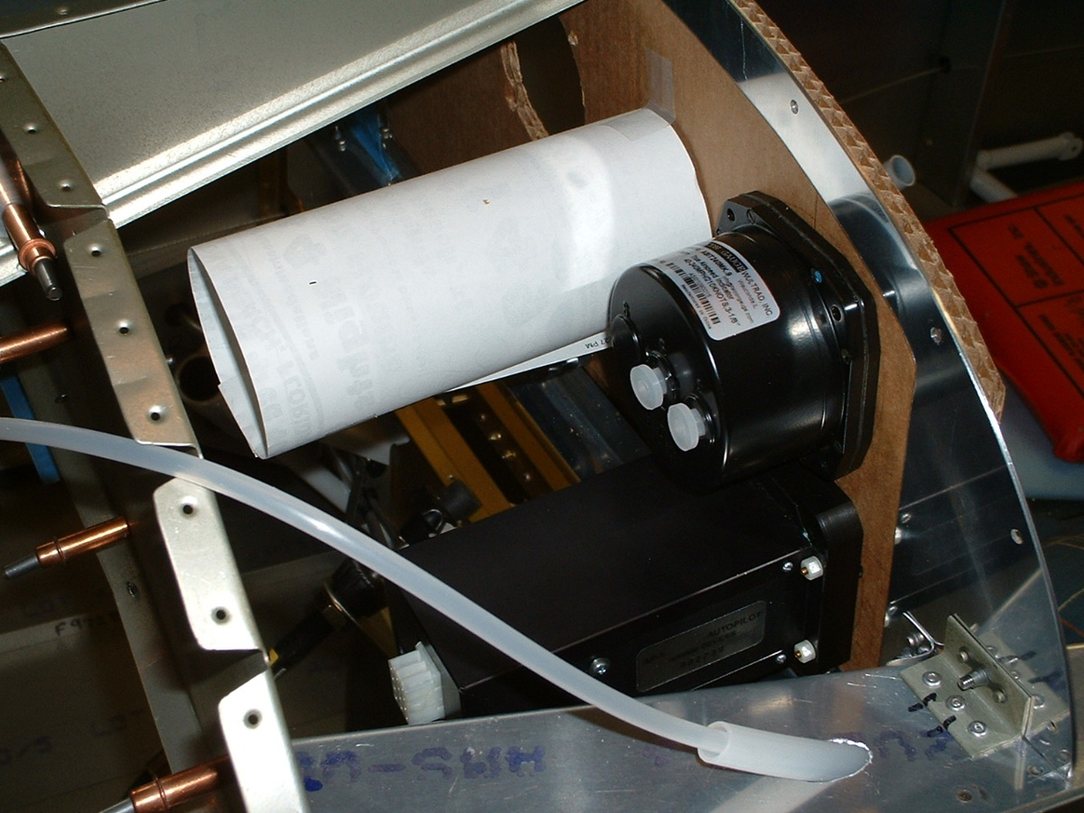
Here is how things look behind the panel. The white paper cylinder
represents the size of the Dynon EFIS unit..
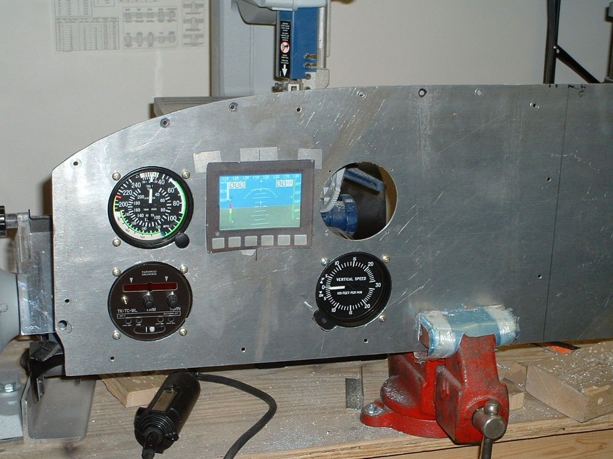
January 7, 2004: After looking at a
cardboard mockup last night, I moved ahead with the first holes in the aluminum panel.
And here it is after the circle cutter and some filing. I will finish the
last hole when the correct altimeter gets back from Van's. I will probably go ahead
with cutting the hole for the Dynon display unit and drill the mounting holes for the GPS
196 in my next session. There is still some cleaning to do on the back side of the
panel where I have been removing the "day glow" orange "stuck on"
surface. I figure any dead weight I can remove will help in the end.
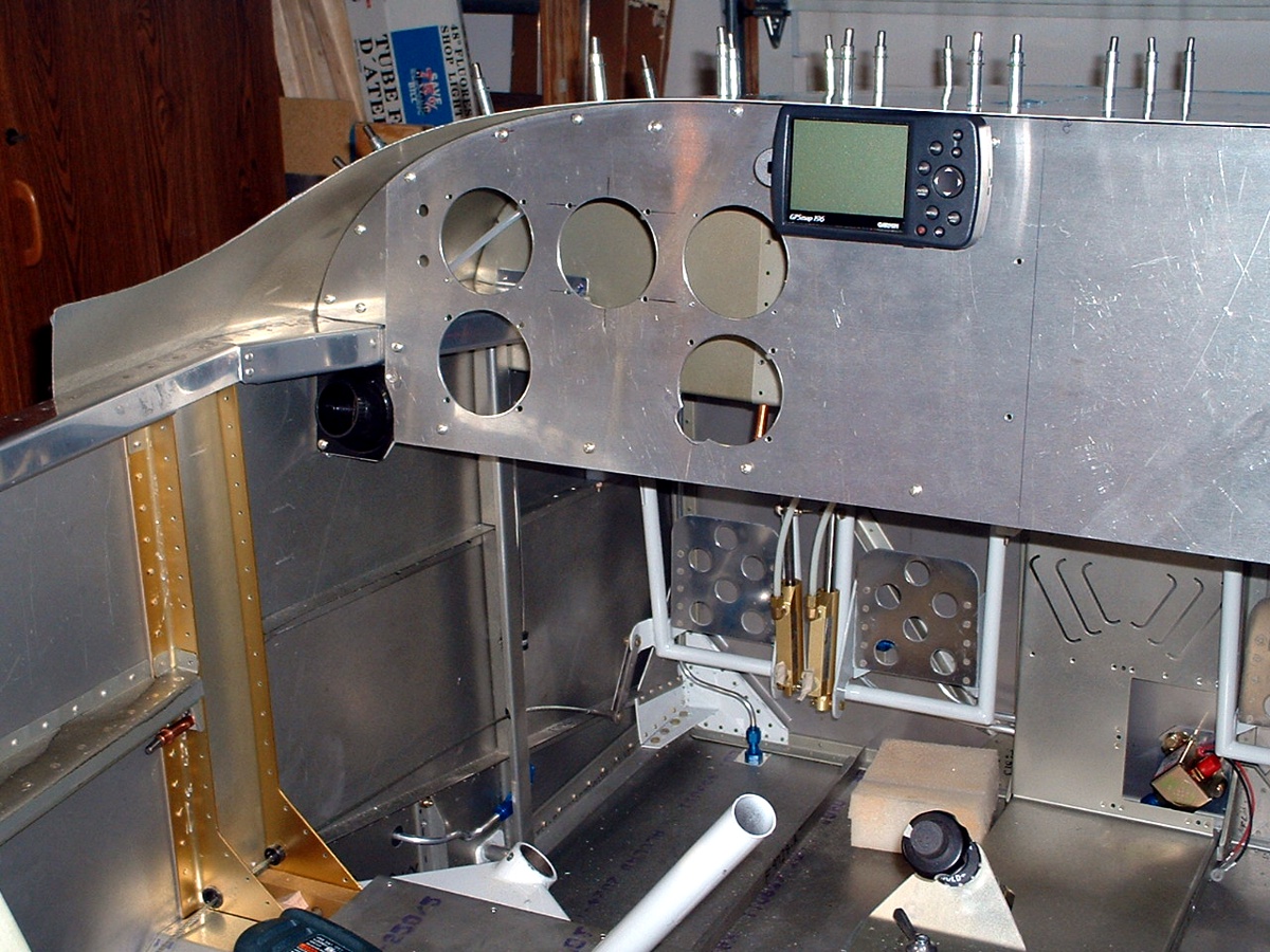
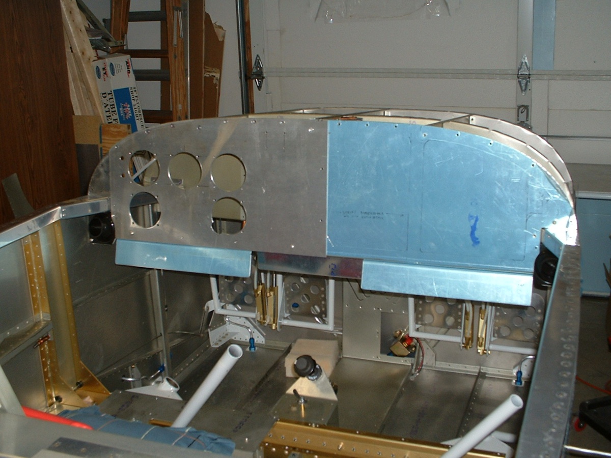
January 8, 2004: This day was used to finish
up the panel drilling and putting in the 3.125" hole for the Dynon color display
unit. I also drilled and mounted the Garmin GPS 196 bracket and made sure that it
would clear the overhang of the forward top skin. I drilled the clearance holes in
the sub-panel for the panel screws that must be left in all the time. Those screws
secure the original control panel frame to the fuselage ribs, etc. After 5.4 hours
today, here is the end result, less all the other instruments in this photo. There
really is a small amount of clearance between the GPS and the aluminum skin that overhangs
the panel. You can also see where I have decided to put the headphone jacks to the
left of the airspeed indicator. If the weather permits me to get out to the airport,
I will go see my friend with the shear to cut the panel to length along the vertical line
you see to the right of the GPS unit.
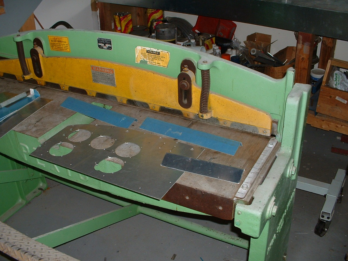
January 9, 2004: I took my panel to the
airport again to shear it to the proper length. I also took the scrap metal from the
original panel with me and made two switch panels to hang below the main panel. Here
are all the pieces on the shear that belongs to Richard
Nadig at the Collegedale airport. Richard is the EAA technical advisor in our
area. He has a metal bending brake right next to this shear. It made
short work of the switch panels. Both of them are visible between the panel and the
shear blades. Van's original throttle plate is shown to the right the new panel I
made.
After all that, here is the final result of the work at the airport applied to
the fuselage interior. The two switch panels are now in place on each side of the
original throttle plate from Van's. I may end up turning the throttle plate around,
but that decision will be made later when I see how far out the knobs protrude.
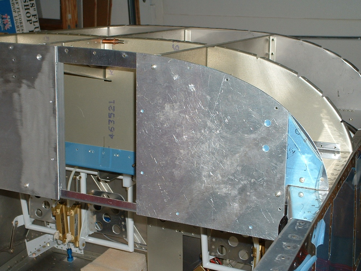
January 12, 2004: I had some time to finish
cleaning the adhesive off the back of the LEFT sub-panel and cut the RIGHT sub-panel to
size after opening up the radio stack in the original F7103 panel from Van's kit.
You can see also that I have riveted in the LEFT rail for mounting the radio stack to the
F7103 panel frame. I have drilled the microphone and headphone 3/8" holes for
mounting the jacks. I will cut out the area behind the RIGHT sub-panel in my next
session. By the way, today's session brings the total aircraft
construction time to 999.1 hours.
| CLICK HERE for fuselage page 37. | RETURN to MAIN MENU |