FUSELAGE CONSTRUCTION - Page 34.
December 24, 2003: The electric fuel pump
arrived while I was off to see Mom on her birthday. The
box was at my doorstep when I got home on the evening of the 23rd. I removed the
instrument panel and supporting ribs to clear the area for more plumbing
installations. With the electric fuel pump in place, I fabricated the fuel line to
run from the fuel tank selector switch to the pump. I then finished cutting the
rigid brake lines running to the firewall to the proper length, then put on all the
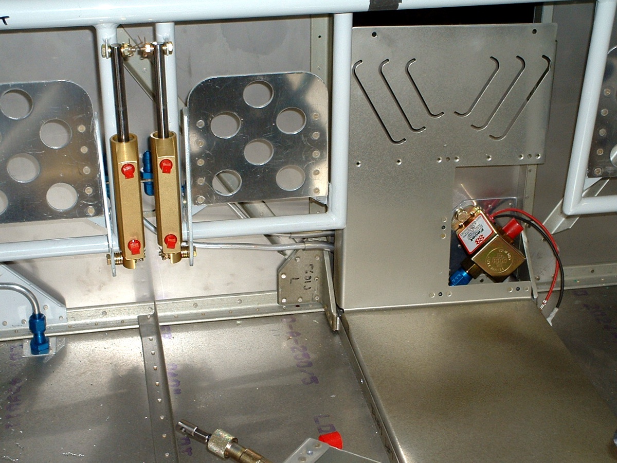
fittings and flared the ends of the various aluminum tubes. In the photo below, you
can see the brake lines emerging from the center floor cover with their plastic tubing
protection applied. Only one of the blue brake line fittings on the firewall is
visible between the rudder pedals. The blue fitting on the fuel pump shows the end
of the newest fuel line. The end of the elevator trim cable is lying on the floor
out of the way from the work area and the floor cover.
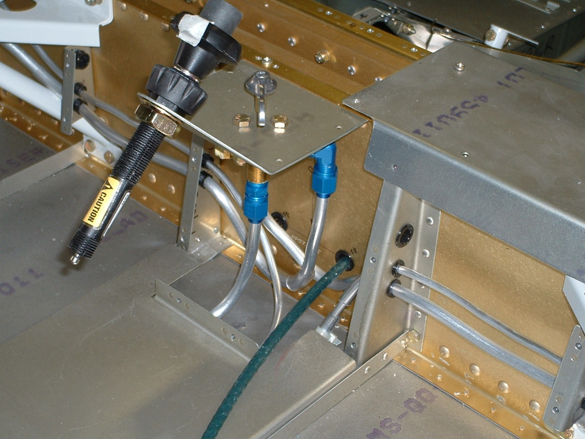
Here is the fuel selector valve with all three fuel lines attached. In
this photo, the LEFT side of the aircraft is on the RIGHT side of the picture. The
fitting for the LEFT fuel tank is hiding behind the output port of the valve. Notice
the bends to make the LEFT fuel line clear the pass-through path of the GREEN elevator
trim control cable. I have again used plastic tubing in places where possible
contact and vibrational wear is possible. The smaller tubing at the right side of
this photo is the left brake line. It comes through that cover bulkhead in the
MIDDLE position and then turns sharply down and runs under the center floor cover.
Since it was so long and convoluted, I sliced a plastic tube lengthwise and wrapped around
the aluminum tube, then secured it to the tube with two tie-wraps. One is under the
cover, the second tie-wrap is visible below.
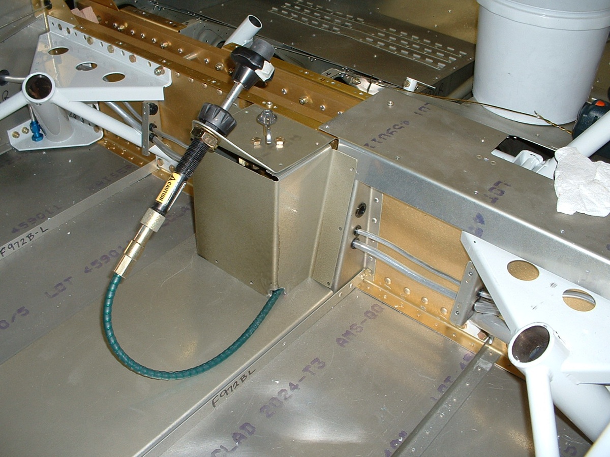
I wanted to be sure that I had enough of a notch cut in the corner of the fuel
valve cover to pass the elevator trim cable through to the wing bulkhead. The notch
needed to be enlarged to ensure enough room to put another plastic tubing shield over the
control cable. I will put that in place when I am ready to screw these covers in
place for good.
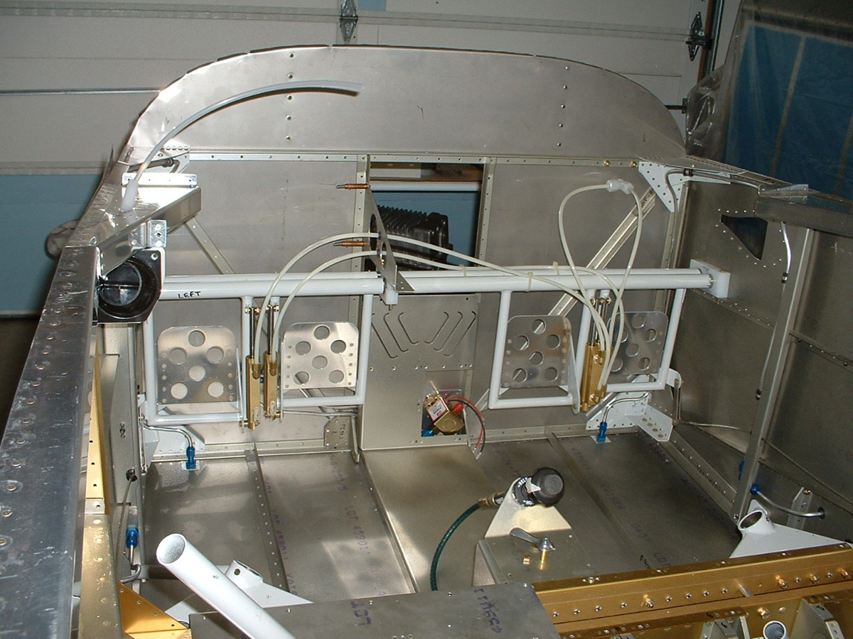
December 25, 2003: What better way to
celebrate Christmas than to give myself a "brake" -- system that is. You
can see that I have managed to complete all the available plumbing for the brakes.
The last two hoses I need are included in the finishing kit. You can see all the
high-pressure plastic lines are now in place. I have taped-off the last two fittings
to keep filings and debris out of the system. I also made a modification to the left
forward canopy deck to pass a conduit containing the static air line upward toward the
location of the altimeter and air speed indicator when they are mounted.
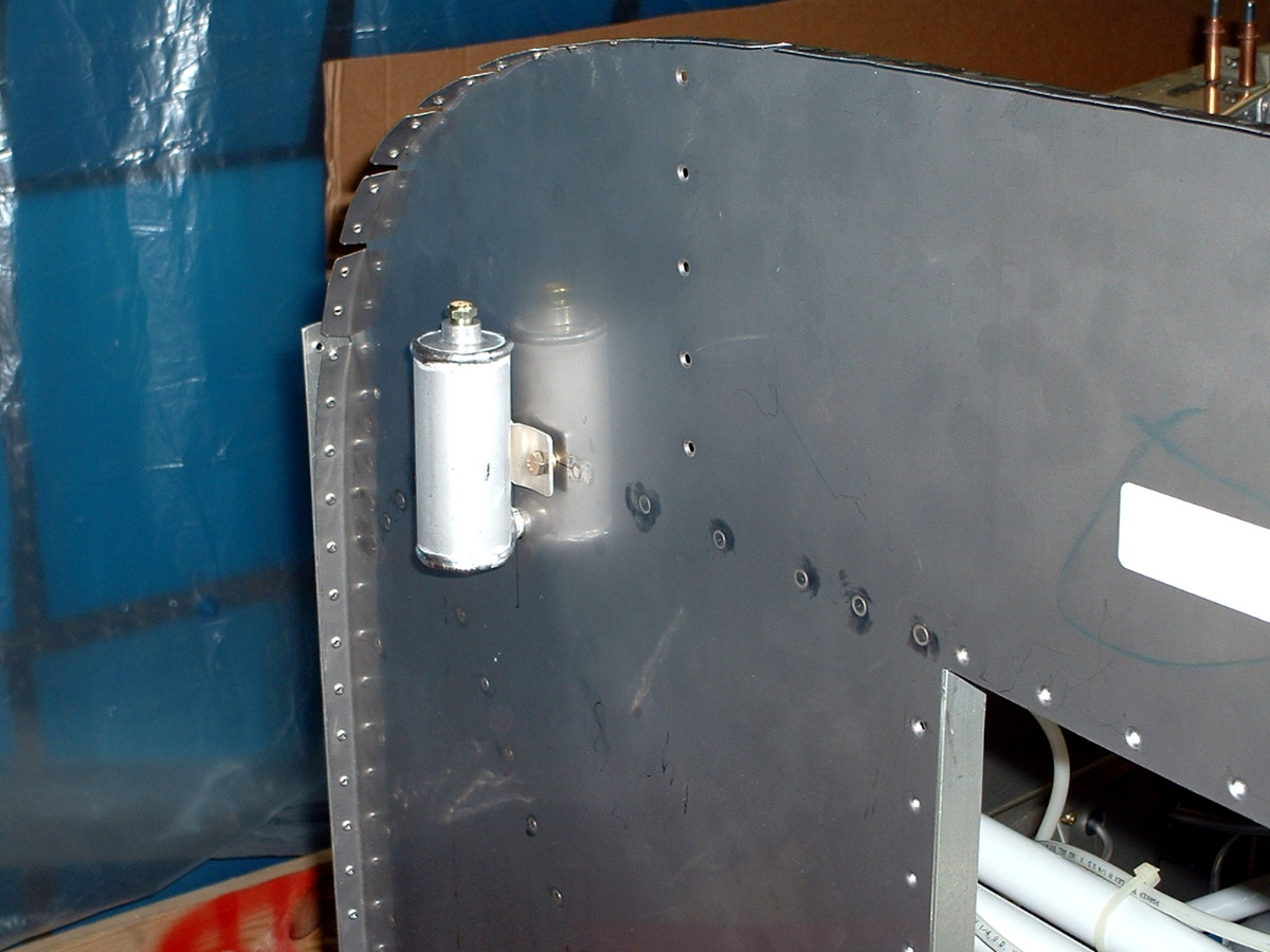
The photo below shows the brake fluid reservoir mounted to the firewall.
The photo above shows a white plastic "T-fitting" with two brake lines leading
down to the brake cylinders. That "T-fitting" is connected to the bottom
of the brake fluid reservoir.
And the last photo today shows the air scoop area of the fuselage skin has now
been cleared of the blue plastic coating and the rivet holes are now dimpled.

| CLICK HERE for fuselage page 35. | RETURN to MAIN MENU |