WING KIT CONSTRUCTION - Photo Page 11.
May 28, 2003: With some of the past few
weeks on the road with the new job, I have been remiss in my work on the RV-9 until this
week. Yesterday, May 27th, the weather was good and I managed to get all the parts
of the flaps and ailerons primed on the driveway outside. Two of the neighborhood
kids dropped by to see what I was doing. The mother of one of them also was curious.
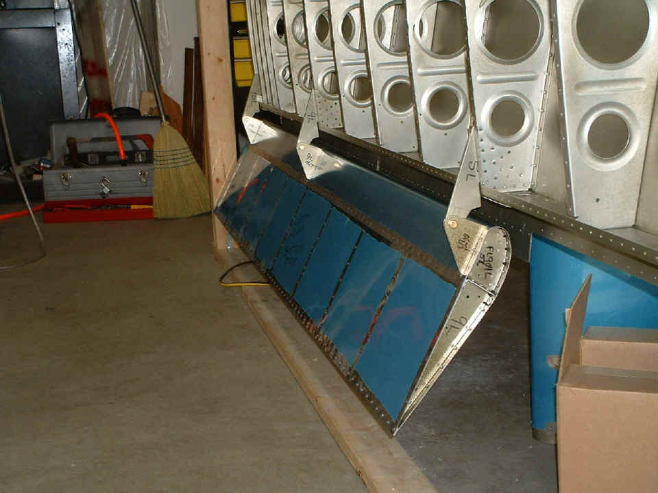
No pix from yesterday, but here is what sits on my bench tonight as of quitting
time. The LEFT flap is coming along nicely. I have riveted the complete spar
and rib assembly together and put on the nose skins and the top skin. As you can see
in this photo, I have just started to rivet on the bottom skin on the special work table
that I built for flap and aileron construction.
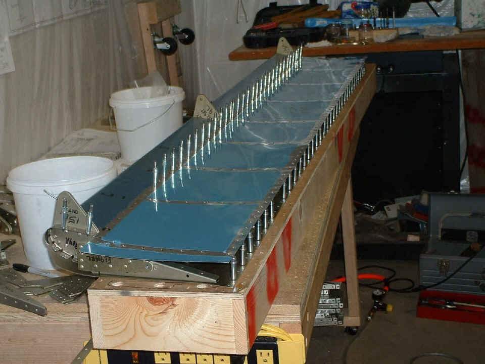
As you can see above, the flap is upside down on the assembly table. I have
clecoed the trailing edge of the TOP skin to the table into the very holes that were used
during the initial assembly a few weeks ago. The other clecos along the spar hold
the bottom skin and nose skins in place as I rivet them all to the spar. I have to
reach inside with a small steel "bucking bar" to form the shop head of the
rivets as I place the rivet gun on the side you see here. I quit work after getting
eight rivets in place. Only the flap spar is riveted this way. The remaining
ribs will be riveted using blind "pop" rivets. The trailing edge will be
back-riveted the same way the elevators and rudder were done in the empennage kit.
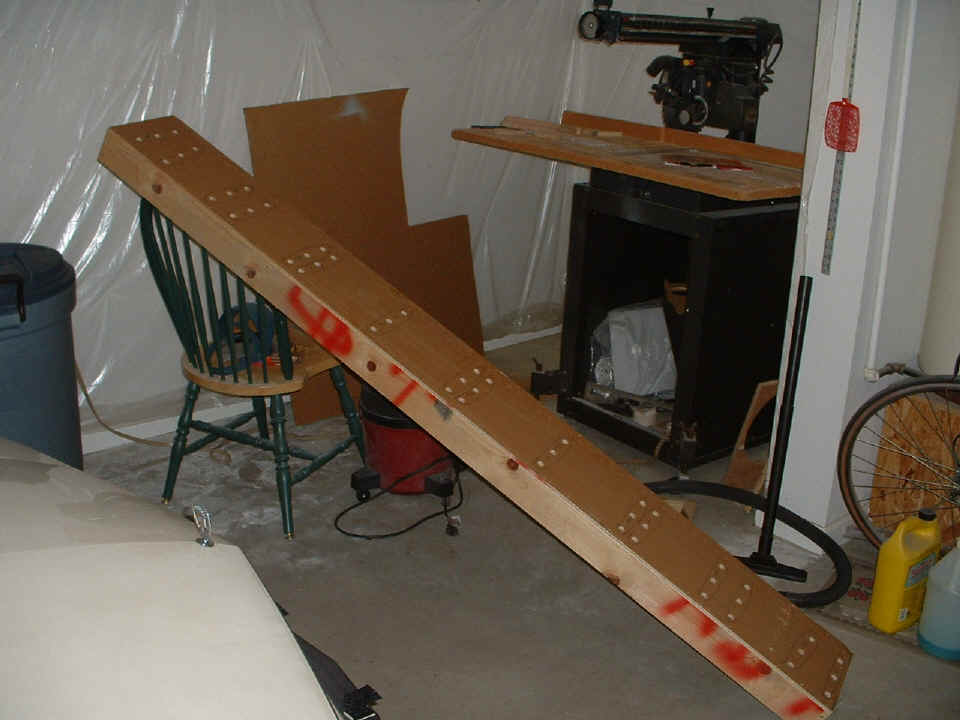
NEW on November 16, 2005: This work table is
built from the long wing spar shipping box I received from Van's. I took the
original shipping box apart and cut it down to the size I needed. The box was taller
when it came from Van's. After cutting one of the long side boards to the length
needed for this building box, I ripped it in half to make it the height you see here.
Each of the lengthwise halves became one side and end of this perfectly straight
and square building box for the flaps and ailerons. You can see in the photo above
that it is longer than the flaps, but not wider. It only has to be wide enough to
allow any clecos to have "passage holes" through the 1/4" lid which was on
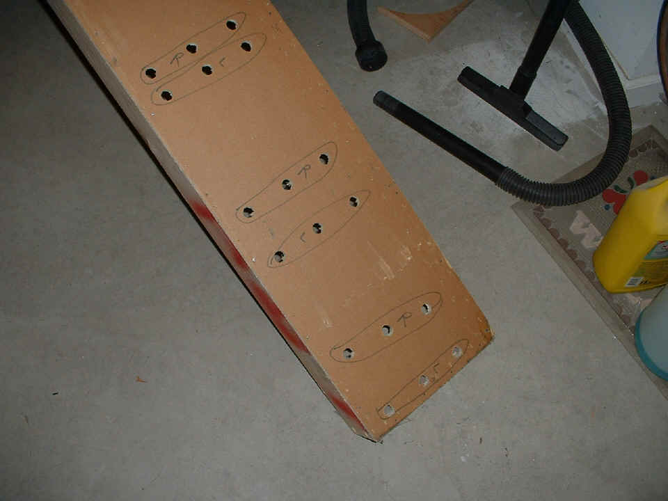
the original wing spar box. Pay attention to the cleco hole pattern below.
Notice that TWO sets of cleco holes exist at most of the locations, but there are three
places where only ONE set of holes were needed. Counting from the aileron end of the
flaps, those three rib locations are the first, fourth, and sixth rib locations.
Also, note that I almost chose a placement of the holes that could have fallen on the
board at one end of the box. That is certainly NOT what you want to happen.
So be sure to place the first rib cleco clearance holes about 1.75 inches from the
end of the box. The length of the box is 88 and 7/16th inches. I don't
remember why it came out that length since 90 inches would work just as well.
Shorter than 88 inches would not work as you can see the cleco passage holes are getting
close to the ends.
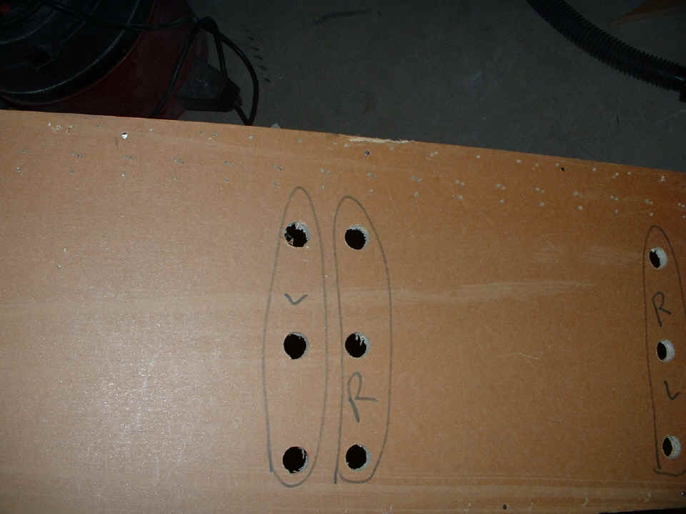
Speaking of getting close to the ends, here is what I am talking about.
The holes at the end are very close to the board across the end. Also notice that
the second set of holes near the end of the box are not square to the edge of the box like
all the others. Those offset holes line up with the inboard flap rib which are
parallel to the side of the fuselage. You will learn all about that later in the
construction of your RV-9/9A.
This close up shows the large cleco holes and the many holes from the trailing
edges of both ailerons and flaps. The cleco holes were only used during flap
construction. You can also see the heads of the one-inch wire nails I used to secure
the 1/4" lid to the boards while building the box for the ailerons and flaps.
The cleco positions were in every other hole in the flap ribs. The holes were
drilled with a flat-sided 5/8-inch wood bit. The holes are clean on the top and
ragged on the bottom (inside the box). There are numerous #40 drill bit holes from
the trailing edges of the flaps and ailerons to cleco them solidly to the box during the
construction process.
Now, where to place the cleco holes? Use a small combination square to get
the holes in a line perpendicular to the sides of the box. Take all the measurements
from the flap skins to be sure how far apart the clearance holes need to be drilled in
both directions along the surface of the box. As you can see, only two sets of holes
will be used for both the right and left flaps. All the other ribs will require
additional holes to pass the clecos into the box while the surfaces of the flaps sit
flush and square on the box top.
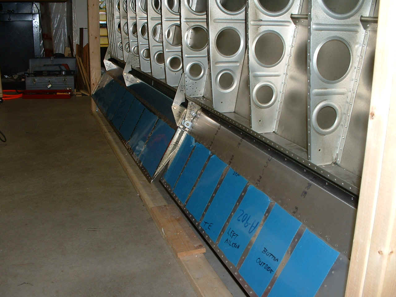
May 30, 2003: I finished riveting the LEFT
flap and hung it on the wing to check the fit of the hinges again. All is still fine
with that alignment. Look Ma, no clecos! I spent a good part of the day doing
my 5th BFR at Collegedale airport. I am good to go flying for another two years.
June 6, 2003: The LEFT aileron is completed and
installed as you can see. I started on the RIGHT FLAP final assembly tonight and
hope to complete it tomorrow (a Saturday) and work on sealing up the LEFT fuel tank, which
I have been putting off for a while. I went flying again last Saturday with two
friends and then to visit my ailing mom on Sunday, June 1st. She is in failing
health and I have spent some time with her this past week. It was good therapy for
me to get back on my project again.
June 10, 2003: I have finished the aileron
and flap for the RIGHT wing and set them aside. I have returned to doing fuel tank
chores. The RIGHT fuel tank now has all its ribs riveted in place. I have to
finish sealing the ribs tomorrow along the shop heads of the rivets and the seams of the
ribs to the tank skin. There are two nose rib reinforcing plates to be installed
with the outside ribs of the tank, which will probably take place tomorrow. I also
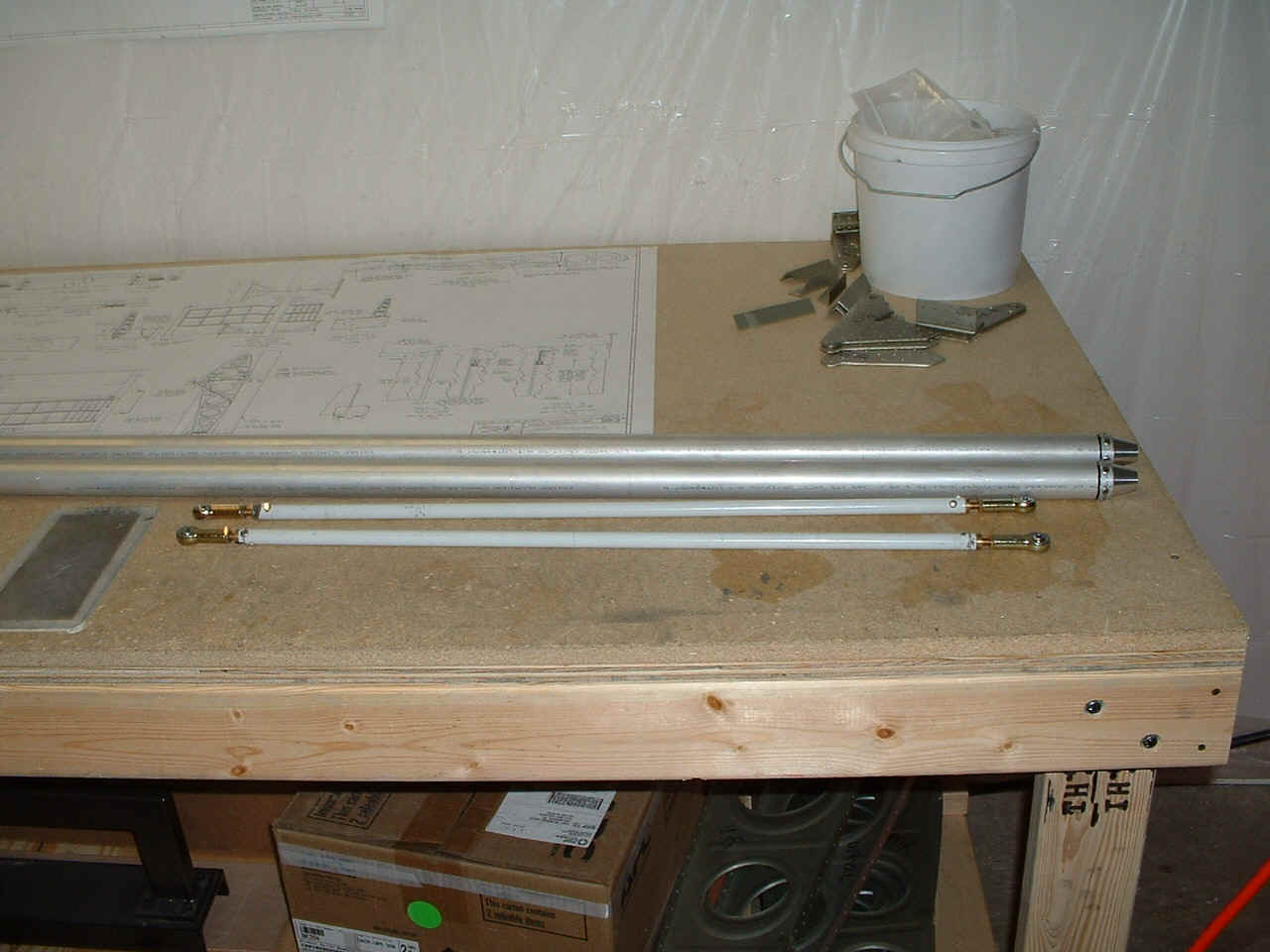
took some time to work on the aileron push rods tonight after putting the fuel tank aside
to let the sealant start curing. Here are the pix:
My total time working on the RV-9A empennage and wing kits now stands at 463.25
hours.
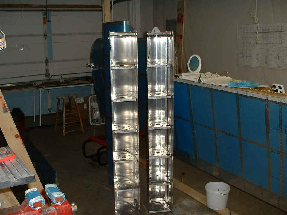
As you can see, the tank on the RIGHT in this picture
is the LEFT fuel tank and it is still waiting for me to
install the rear baffle plate. I thought I would leave it off until I get the second
tank completed to the same stage of construction. The tank on the left still needs
the fuel sensor plates, vent line, and fuel pickup tube installed. When the LEFT
fuel tank is completed, it goes on the wing in this picture, then the wing goes into the
storage saddle to make way for the final assembly of the RIGHT wing on the construction
jig. That should go very quickly since the parts are all match-drilled, primed and
ready for me to start riveting.