WING KIT CONSTRUCTION - Photo Page 7.
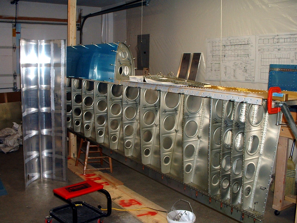
February 17, 2003: Here is the RIGHT wing on
the construction stand. You can see the green tint to the aluminum skins where I
primed all the inside surfaces and the ribs. I have left the blue protective
covering on the outer surface of the skins for now to minimize scratches to the surface.
You can also see the inside of the wing tank is NOT primed, but I have used a
Scotch Brite wheel to scuff up the areas where the tank sealant will be applied to bond
with the tank ribs and rear baffle plate. I also had a chance to drill the holes for
the fuel filler flange and drain port on both skins..
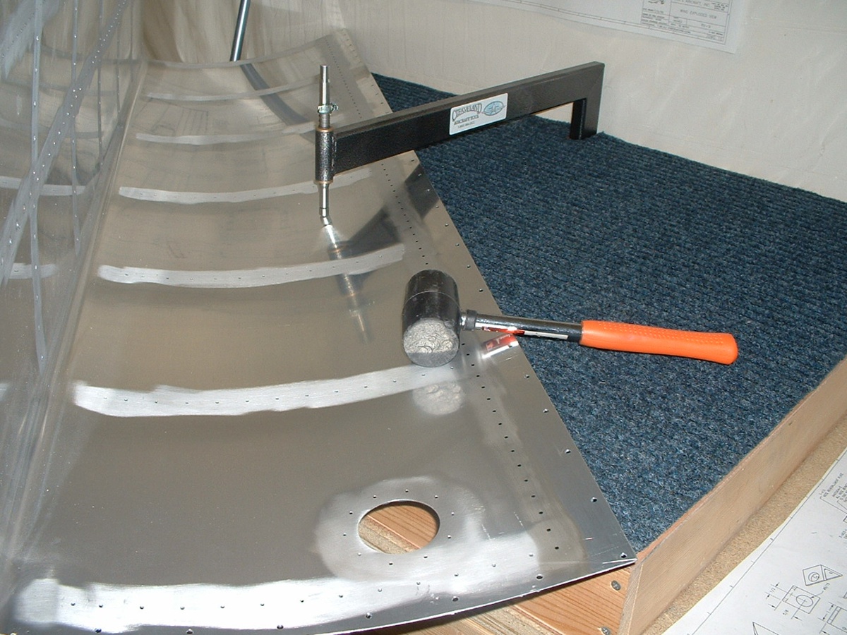
The dimpling table and "C" frame ready to resume speed when I get a
chance. I only had time to dimple one side of one tank skin. You can see the
scuffed up areas really well in this photo as well as the fuel filler cutout in the skin.
I ordered a can of tank sealant from Van's today along with two of their ready-made
fuel pickup tubes with the stainless steel filter mesh on the ends.
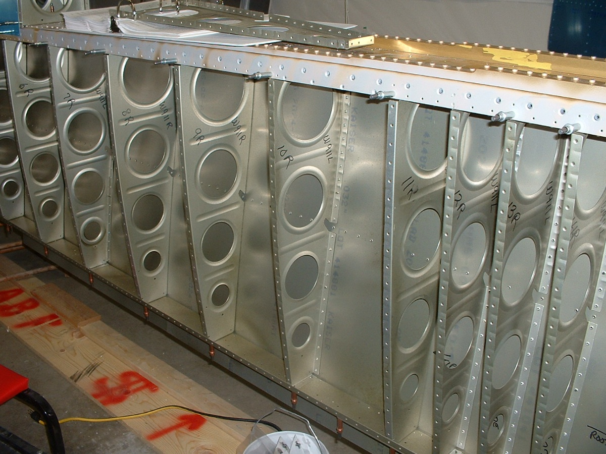
Here is a close-up of the green-tint primed aluminum area inside the wing.
You can see how the ribs will be riveted to the main wing spar here. And of
course, you can see how I numbered all the ribs to be sure they go back in the same places
where they were match-drilled to the wing skins.
February 23, 2003: I spent most of this past week
going to and from Texas for a trade show and some job opportunities. I got a chance
to work 5.1 hours today on the fuel tank skins and on the landing light installation for
the RIGHT wing. I finished the dimpling of all the remaining rivet holes in the fuel
tank skins. Since I am awaiting delivery of the fuel tank sealant, I turned to the
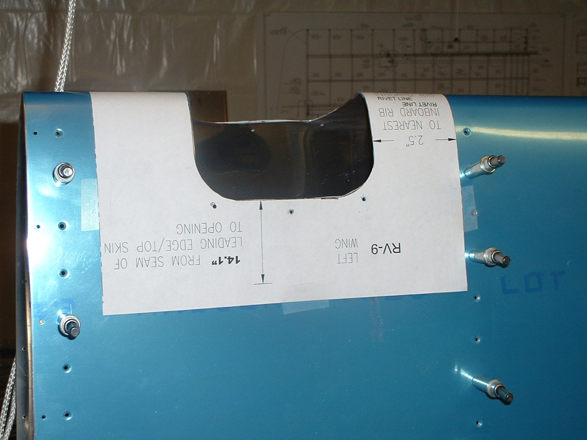
landing light installation. You can see where I have put the template back over the
landing light hole in order to drill the lens attachment holes in the proper place.
This is the underside of the RIGHT wing. Van's uses one template for both
wings. It is turned one way for the left wing, and the opposite direction for the
right wing.
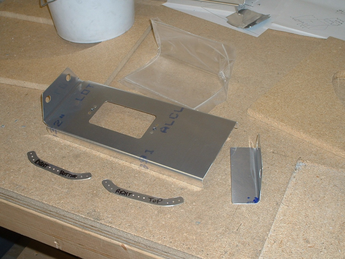
Here are the landing light brackets with plate nuts already attached to the
larger one. RV-9 builders have to trim the larger piece to fit the kit into the wing
between the two outer-most ribs. The two smaller brackets will attach the Plexiglas
lens to the wing skin when the installation is completed. They were used as
templates to match drill the holes in the wing skin in the photo above. There are
some holes to be drilled in the two larger aluminum parts when the pieces are mated to the
wing nose ribs. That chunk of aluminum in the top of the photo is the scrap from the
hole I cut into the leading edge of the wing. The 55-watt halogen bulb and reflector
that fit into the rectangular cut-out below are not shown.
| Click for wing page 8. | Return to MAIN MENU |