WING KIT CONSTRUCTION - Page 3.
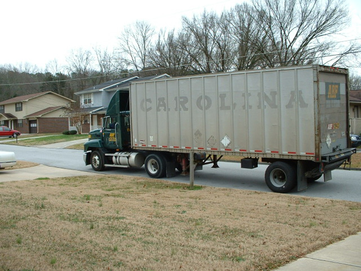
December 27, 2002: The wing kit is enroute via ABF Freight Lines from Portland, Oregon to Albuquerque on the first leg of the cross-country trip to my place here in the Chattanooga, Tennessee area. Delivery is scheduled for January 3rd, 2003.
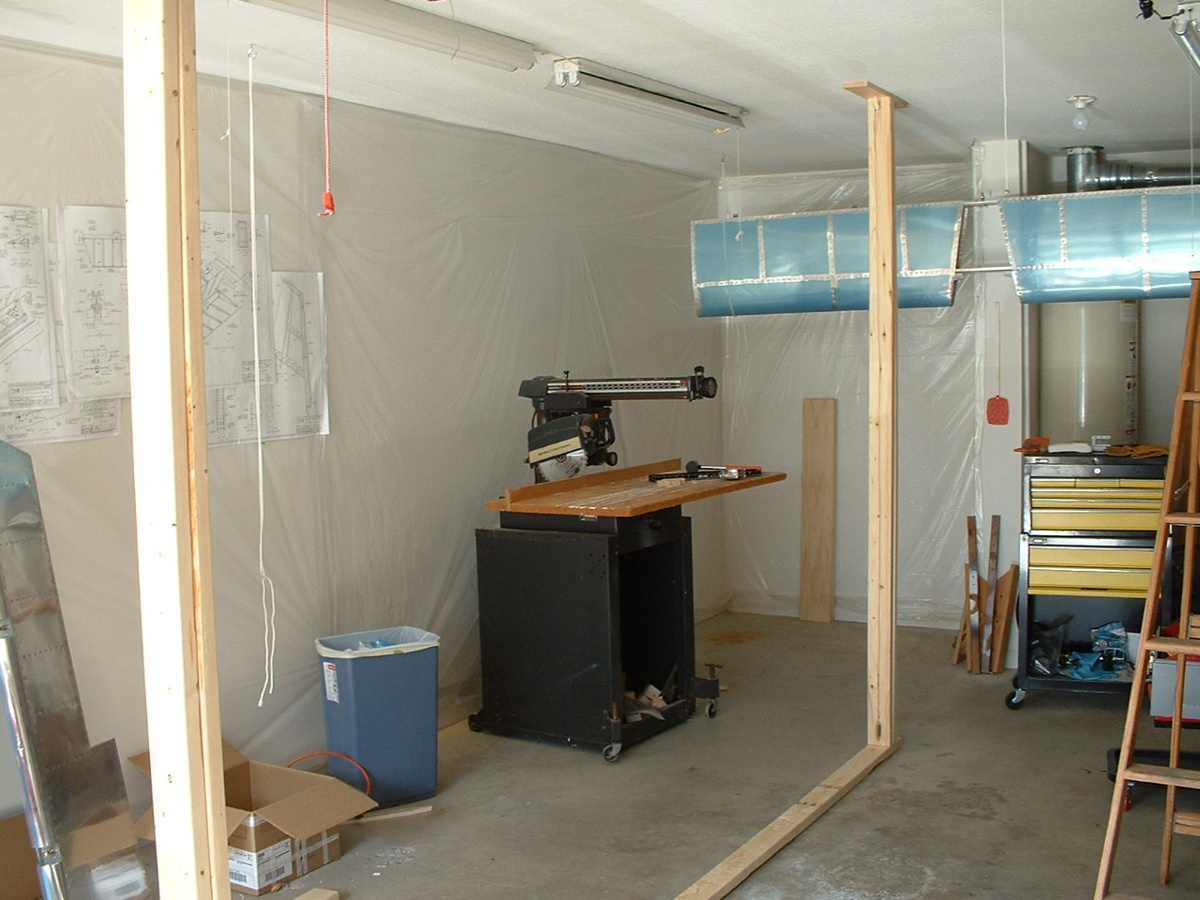
January 1, 2003: Latest report has the wing kit in Little Rock, scheduled for an overnight run to the Atlanta area. Here is the beginnings of my wing construction area. I got started on it today.
January 2, 2003: I finished squaring up the pairs of two-by-fours with each other, then rolled the saw away and put the work table back in its normal location to work on the fiberglass tips. As of 11:15 PM, the two crates are in the Atlanta ABF freight terminal loading to come to Chattanooga.
New information added October 26, 2004: The wing jig above was installed with the NORTH end of it just under 5 feet from that part of the wall that sticks out from the water heater area where the RED fly swatter is hanging. From the fly swatter location to the garage door behind my camera location, it is about 24 feet. There is a 3/4" thick board at the top of each 4x4" post at the ends of the wing jig to secure it to the trusses above. That board is screwed to the bottom of the roof truss just above the dry wall ceiling. There is a 12-foot long 2x4 assembly on the concrete floor. It is made by joining an 8-foot long 2x4 and a 4-foot length of 2x4 using a 3/4" plank as seen further down the page in the photo with the unopened wing crates. IF you have a 12-foot long 2x4, use it instead of what I did using the lumber I had on hand. The posts have 1.5" right angle steel brackets on both sides securing the 4x4 posts to the ceiling planks and to the 2x4 on the floor. I want to stress that the length of the upright 4x4 posts are cut to be just tall enough that they are "pressed into place" between the 2x4 on the floor and the brace on the ceiling. Think of them being about 1/8 of an inch taller than the space available between the floor 2x4's and the board screwed to the roof trusses. The 2x4's on the floor are not attached to the floor, just pressed down by the posts between the roof trusses and the concrete floor. The upright posts are NOT the same length since the garage floor is sloped DOWN slightly from the back of the garage toward the garage door. The posts are PLUMBED to be perfectly upright in both directions. When everything at both ends was aligned, I used a RED marking pen to DRAW LINES on the concrete floor showing the exact location of the 2x4 to be sure it would NOT MOVE during wing construction. Those marks are still there today (October 26, 2004) although the wing jig has been removed when the wings were finished. The south end of the floor 2x4's measured 92 inches from the garage door. The upright 4x4 posts sit ON TOP OF the 12-foot length of the 2x4's on the floor. Van's plans provide the spacing between the posts for each type of wing. As I recall from memory without checking the plans, that was 133 inches for the RV-9 wings.
As of the time of this update of information October 26,
2004, the fuselage is built with the engine and propeller installed. The
front of the propeller is about 3 feet from the garage door. With the tail feathers
off the fuselage, I have about 2 feet of clearance between the tail cone of the fuselage
and my tall roll-around tool box to move around at that end of the airplane. Just to
let you see how things have changed, here is a current photo of the garage area. The
garage door comes down about 3 inches this side of the white folding table seen at the
bottom of the photo. That leaves about 18 inches to walk between the white table and
the prop. There is about 6 inches of room between the RIGHT landing gear and the
wing jig cart at the LEFT side of the photo, and about 9 inches of room between the LEFT
landing gear and the short file cabinets seen at the RIGHT side of this photo.
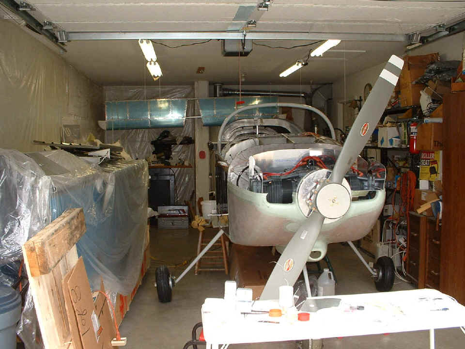
End of the October 26, 2004 update. You have to look at the
remaining pages to see how I got this far. ;-) The photo above also appears on
page 62 of this web site.
January 3, 2003: The wing kit has been
delivered and I am starting the inventory of parts in the two wooden crates.
The 2x4 inch studs have been cut to the proper link to
be secure between the concrete floor and trusses above in the garage.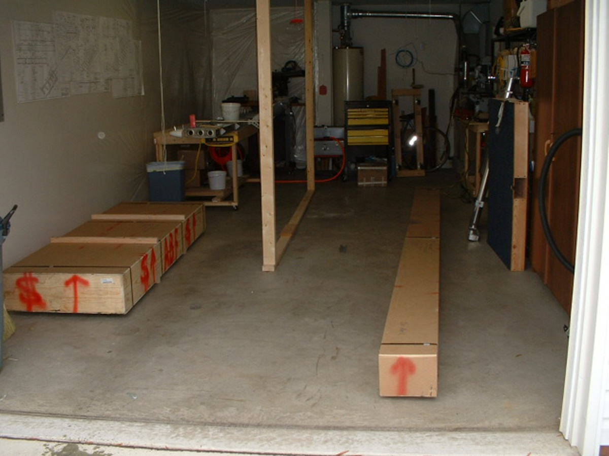
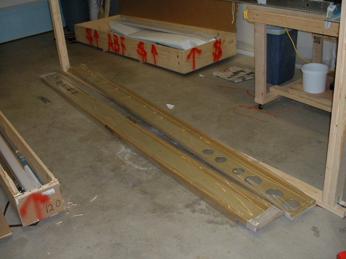
The main wing spars just waiting until I can get started. September
3, 2017: The image above has been modified to remove two lens flare
artifacts from the original image. This was done as part of image upsizing
to 1200 x 900 pixels across the web site.
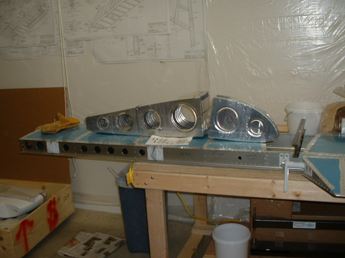
Nose ribs and main wing ribs sitting on top of the horizontal stabilizer.
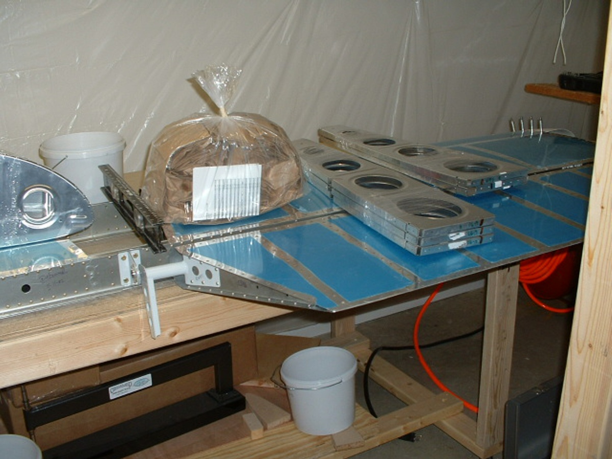
More ribs and the many little bags of hardware, which have all been checked and
put away into their mini-boxes on the shelf.
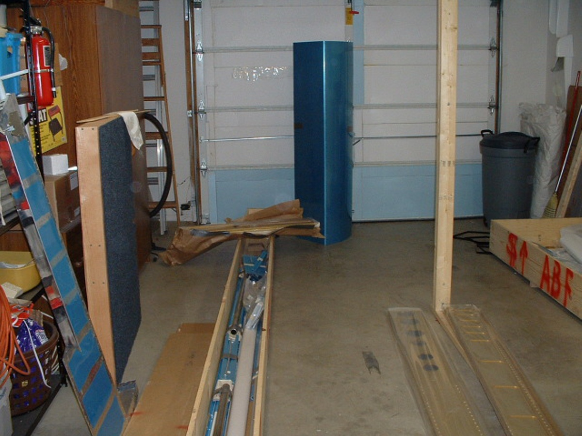
The leading edge wing skins and the fuel tank skins stand at attention by the
garage door. Seen in the photo above Many other long thin parts are still in the wing spar box awaiting
inventory.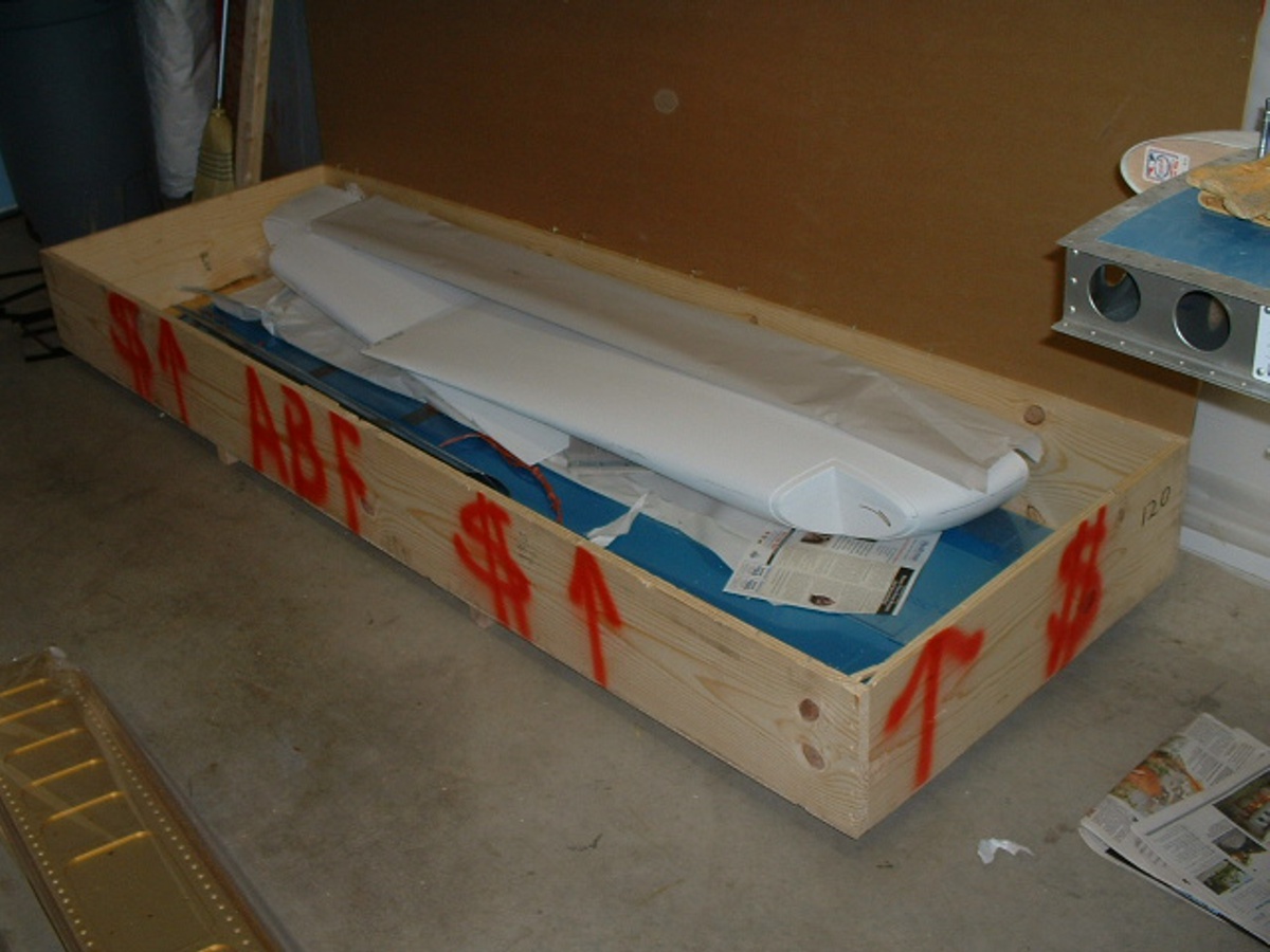
The 8-foot box still has the remaining wing skins in it along with the two
fiberglass wing tips. And if you look closely, you can see the most recent thing
that I did to the left fiberglass tip on the horizontal stabilizer. Yes, that is a 1/4" thick balsa plank that I have cut to fit into the back of
the glass tip. I have the fiberglass cloth, but need to get some epoxy to finish
that tip assembly before riveting it onto the horizontal stabilizer.
| CLICK HERE for WING PAGE 4. | Return to MAIN MENU |