Updating Olson Technology headend units with 098-000090 power supply · · PAGE 1.
Revised on October 14, 2011: The present
power supply used in Olson OTM modulators and OTR processors is the 098-000090 power
supply, also known as 98-90 inside the Olson facility. The photos below show how the
new 24-volt DC power supply is installed in the existing power supply assembly.
September 1, 2021: It is almost 10 years since I
published this web page. The 98-90 power supply is no longer
available from Olson Technology. Any 24-volt DC output switching mode
power supply of the correct size should work. If you are purchasing a USED
LCM-6550 triple modulator, check to see if it already has the power supply seen
in the photos below. If you see a power transformer and some large
electrolytic capacitors, the unit is not up to date. The LAST photo at the
bottom of this web page shows a six-inch measuring stick for size comparison
against the length of the new switching-mode power supply
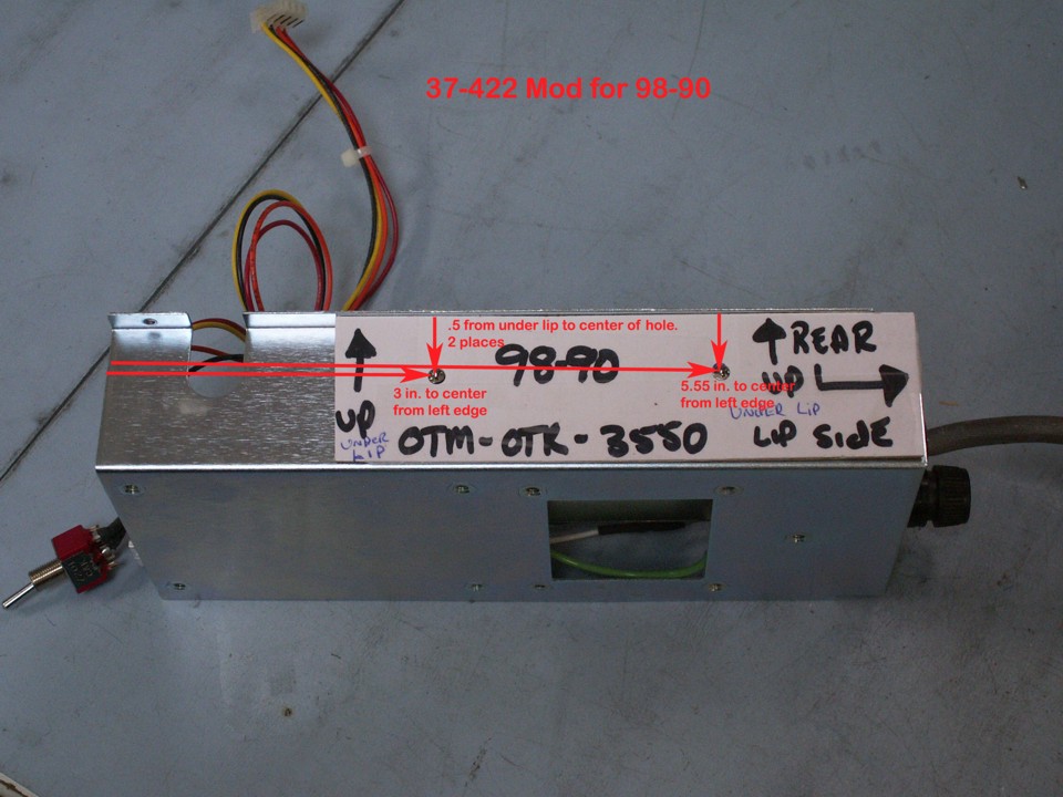
The older 98-60 "brick" switching-mode power supply is mounted in the
metal bracket, part number 10-94 as seen below. The new 98-90 power supply needs two
NEW screw holes drilled in the metal bracket. The two mounting screws are provided
with the new power supply module. Please take notice of the power cord and fuse
socket at the right side of the photo and power switch seen on the left side of the
photo. The white label in the photo indicates the orientation of the sub-assembly
inside the main chassis. Both holes that need to be drilled in this bracket are
one-half inch below the lip (0.5 inch). The first hole is 3 inches from the
"front" of the sub-assembly. The second hole is 5.55 inches from the
front. You will need to remove the old 98-60 power supply before drilling
these new holes.
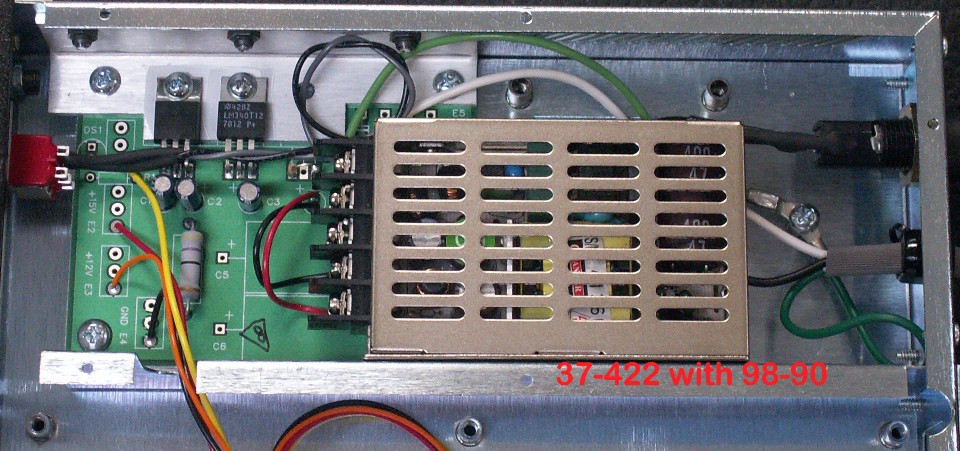
The part number for the entire power supply sub-assembly is 37-422. In
this photo, the front of the 19-inch wide chassis is at the left of the photo. This
view is looking down at the new 98-90 power supply mounted in place inside the chassis.
It has come to my attention that some of you have VERY OLD
modulators, processors, or demods that have the original discreet component power supply,
not the previously used 98-000060 "brick" power supply. The photo below
shows where the two large axial electrolytic capacitors were installed in those oldest
designs. If you have one of those units, you will remove the large capacitors at
locations C5 and C6 since they have dried out and you now have HUM BARS rolling upward on
your television screen. The oldest units also have a power transformer mounted on
four standoffs in the chassis. Remove that old iron power transformer to make way
for the new switching-mode power supply. Two of those transformer standoffs are
visible in the photo below near the green and white wires coming from the rear of the
chassis. The "brick" power supply seen below obscures the location of the
bridge rectifier diodes which also need to be removed from the circuit board.
Capacitor C4 is removed to make way for the red and black wires. Connect the RED
wire to the positive ( + ) location of C4 and the BLACK wire to the other C4 wire
location.
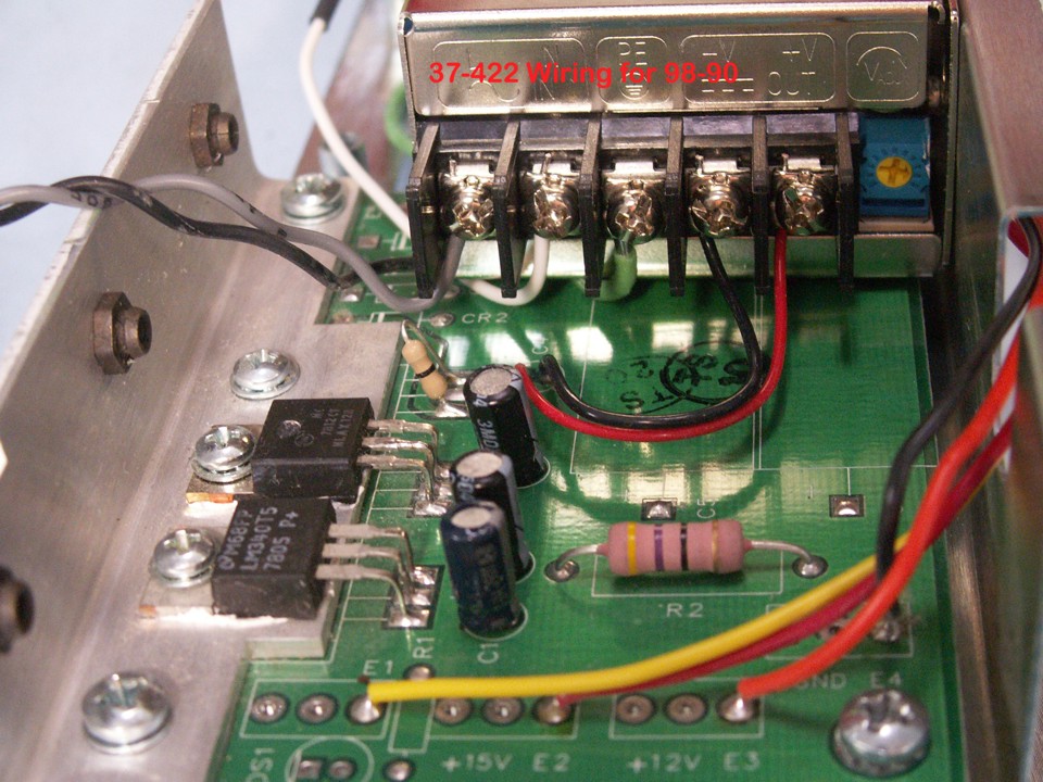
The photo below shows the end view of the power connections to the power supply
circuit board and from the AC mains. The gray and white wires from the power switch
attach to the left most screw terminals for AC input voltage. The green wire from
chassis ground goes to the center screw. Notice the universal symbol for GROUND in
this picture. The RED and BLACK wires from the circuit board connect to the
remaining two power supply voltage screws. The RED wire is under the screw
below the +V OUT label. The BLACK wire is under the screw below the -V
label. These FIVE wires are all the connections that are needed to the 37-422
power supply sub-assembly. Any other voltages needed to operate the OTM / OTR units
are generated on the 37-422 board. If you are modifying an older unit where you had
to remove the power transformer, rectifier diodes and the large electrolytic capacitors,
you have two more things to do. Look at the photo below and you will see ONLY TWO
voltage regulators. The third 24-volt DCregulator has been removed since the "brick"
power supply now provides that 24 volts DC voltage. You will also see a ZERO-OHM
resistor with one black stripe on it, not the usual three or four color coded bands on
normal resistors. That zero-ohm resistor can be a short piece of wire that connects
the circuit board traces that WERE the input and output connections for the
24-volt DC regulator that
is no longer needed. Remember that the connection on the CENTER pin of the voltage
regulators is connected to GROUND. Be careful that your wire flies OVER the center
trace for the removed regulator.
This last photo shows how a 3-inch white wire was added to the power cord to
reach the AC input screw terminal on the power supply module. A piece of heat
shrink was placed over the solder connection to the wire.
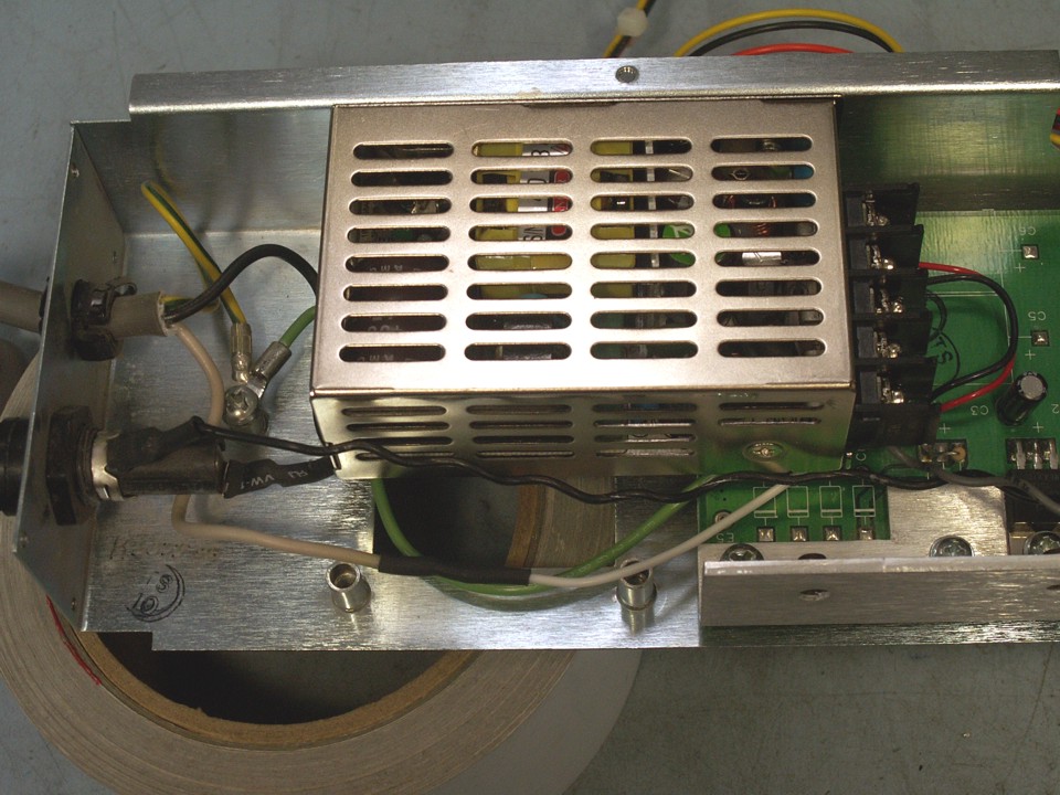
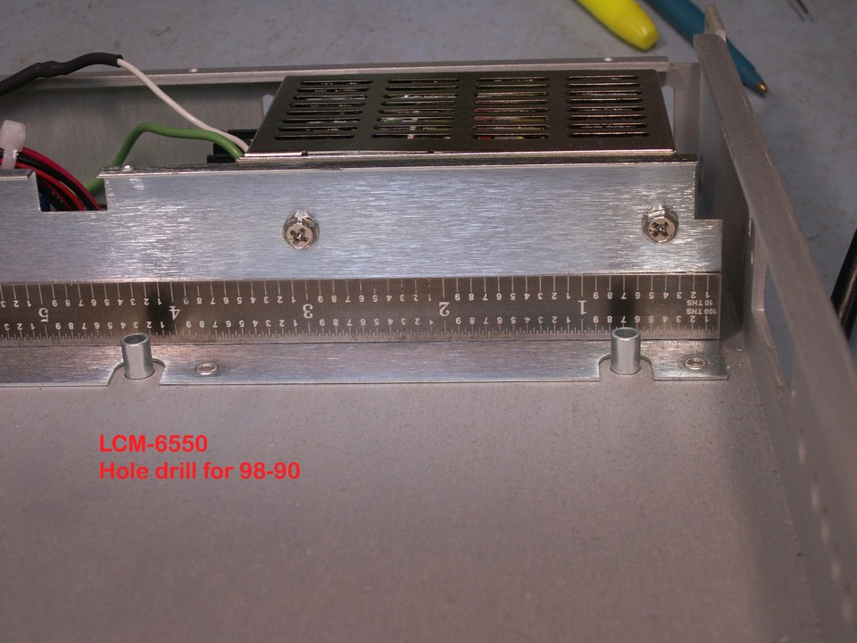
Olson Technology LCM-6550 power supply mounting holes.
If you are installing the 98-90 power supply into an LCM-6550 modulator, the
photo below shows some minor differences in the mounting process. Notice where the
3-inch hole is located 1/2-inch below the lip of the bracket, and how the second screw is
only 0.45 inches from the end of the mounting bracket. The power
connection wires are shown in the photo for orientation. The two screws shown below
are provided with the new power supply. The "universal" power supply works
on 50 Hz or 60 Hz line power from 100 volts AC input to 240 volts AC input.
If you have additional questions, please contact me.
Jerry K. Thorne
Senior Application Engineer
Olson Technology, Inc.
jerrythorne@olsontech.com
423-883-7834 Eastern Time Zone USA
SKYPE NAME: n2prise