Using RF Amplifiers for Isolation Page
2
        Figure 3.
  CLICK for Larger
PRINTABLE Image
Figure 3.  Click above or here for larger printable graphic.
Figure 3 is similar to Figure 1 except that distributed gain is used to isolate one channel line up from another.   The hybrid inside the isolation amplifier will provide REVERSE isolation typically equal to the gain of the hybrid plus 5 dB.  When matched closely to the impedance of the 15 dB directional coupler, the combined reverse isolation path can easily reach or exceed 60 dB.  Generally, the lower the frequency the better the isolation.  The input pad and equalizer will provide signal level control to insure optimum carrier-to-noise across the full bandwidth.  The second directional coupler serves as a test point to insure that the local group of channels will match the signal level of the main group of channels.
The second amplifier in Figure 3 raises the signal levels high enough to reach the laser transmitters with the correct input levels.  The amplifier in this example is a single-stage QRAM amplifier, which can have a quadra-power or feedforward hybrid configuration.  The input pad and equalizer determine both the input and output signal levels.
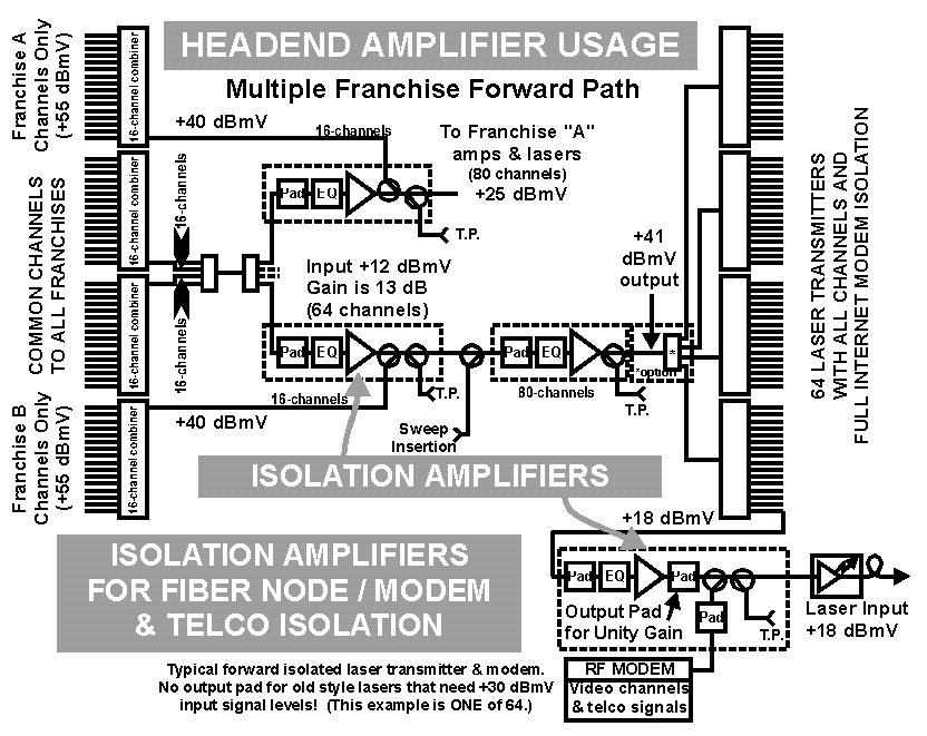
The final headend forward path diagram shown in Figure 4 is similar to Figure 3, but adds a final layer of isolation at the node level.  In this section, each and every node is isolated from all other nodes to prevent RF modem and telephone signals on the same frequencies from interfering with similar signals on other fiber nodes.  The gain of these final isolation amplifiers is chosen based on the required input level to the laser transmitters.   Older lasers that require +30 or +32 dBmV input signals will use either 13 dB or 17 dB gain isolation amplifiers.  The more modern lasers that require input in the range of 17 dBmV will only use the 13 dB gain models with an OUTPUT PAD between the hybrid and the combining directional coupler.  When this is the case, the pad value should be chosen to assure that the actual input and output levels at the hybrid are in the "sweet spot".  That level is typically at 3 to 5 dB above the noise figure of the hybrid. This level should insure a good composite triple beat performance.  If CTB is not a major concern, the signal level may be raised to add to the carrier-to-noise ratio.  Since this is a single-stage amplifier, a balance between acceptable CTB and C/N must be considered.
< NEXT PAGE >
        Figure 4.
  CLICK for Larger
PRINTABLE Image
Figure 4.  Click above or here for larger printable graphic.