Fiber Optic Fundamentals - PAGE 4.
The last part of Fiber Fundamentals deals with optical signal strength received at the end of the fiber. To put it simply, match the transmitter optical power to the fiber losses, and arrive at the optical receiver with the proper optical signal level. We design our systems to "The Sweet Spot" for the best optical-to-RF conversion performance. The PDF diagram found HERE shows a couple of schematics of two-way fiber optic links for CATV service over single-mode fiber.
To compute the loss of the fiber you need to know the loss per mile, kilometer, or per 1000 feet. For SMF-28 fiber, those numbers are 0.56 dB per mile, 0.35 dB per kilometer, and 0.106 dB per 1000 feet of single-mode fiber at a wavelength of 1310nm. For now, let's just consider 1310nm systems. There are other issues to deal with when discussing broadband RF transmissions at other wavelengths between 1470nm and 1610nm. We shall save that for another article.
Let's consider two simple fiber links. One will have a single fiber with a length of 26 miles. The second one will have a single optical transmitter sending broadcast CATV signals to eight different receive locations much closer to the transmitter.
For the 26-mile path, the fiber loss is rated at 14.56 dB. The next question is how many fusion splices are in the 26 miles of fiber? That depends on the size of the fiber cable reels used in the construction. Let's assume 1 splice per mile, which would mean 25 splices. A good fusion splice has a loss of approximately 0.05 dB or slightly less. Using the worst case number, we get splice losses totaling 1.25 dB. That brings the loss of the 26 miles of fiber to approximately 16.1 dB. The last requirement is for fiber optic jumpers at each end of the fiber. A good clean mechanical optical connector has a typical loss of 0.2 dB. With a pigtail at each end fusion-spliced directly to the fibers entering and leaving the buildings, you can keep that additional loss to about 0.5 dB. That gives a total loss from end-to-end of approximately 16.5 dB. Add about 0.1 dB for the length of the jumpers. If you use bulkhead patch bay connectors at each end, you can increase the total loss to about 16.7 dB. The received optical power should be about -1.7 dBm. That level is within 1 dB of the "sweet spot" for a good optical receiver that performs best at -1 dBm received optical power.
For a simple system feeding eight receiving locations, any distances in the 1- to 2-mile range will have most of the loss in the optical splitter, not in the fiber between buildings. The length of the fiber is less important in that situation. These type of systems are common for college campus or other multiple building properties like hotels or hospitals. An eight-port optical splitter will have a loss just under 11 dB. A 12 dBm optical transmitter will overcome the splitter loss, plus the three fiber jumpers needed to connect from the transmitter to the splitter, then to the patch bay where the fiber leaves the building, and the last of the three jumpers at the patch bay at the other end to the optical receiver. The goal of getting within 1 dB of the optimum receive level is achieved.
Having the correct optical power at the receiver provides the best combination of carrier-to-noise performance versus CTB, and CSO distortions. The result is the analog television pictures will not look snowy or have lines in the pictures, or blocky squares in the "digital" channels. The RF signal level from an optical detector will vary 2 dB for every 1 dB change in the received optical power level. The end result is for 1 dB of light power level change: a 2 dB change in C/N occurs, and a 4 dB change in CTB occurs. That is why it is important to hit the "sweet spot" optical power level reaching the optical detector in the receiver. Too much power and you get the third-order CTB distortions and lines in the picture from signal overload. If the received optical level is too low, snowy pictures are the result, or the digital channels will be intermittent, tiling, blocky, or not work at all.
All Olson Technology analog RF fiber receivers are calibrated to have 1.0 volts on the DC test point when 1 milliwatt (0 dBm) of optical power is received by the optical detector. The best RF performance is achieved at -1 dBm received optical power when the DC test point reads 0.79 volts. The high-impedance input of a digital volt meter is required for this measurement. Do not use a volt meter with a needle pointer since they have a lower impedance and will provide erroneous readings.
Remember the three basis rules for RF transmission over single-mode fiber:
1. Provide the correct RF input signal level to the fiber transmitter.
2. Match the transmitter laser power to loss of the passive optics, connections at
bulkheads, and the loss of the fiber over the path.
3. Arrive at the optical receivers with the correct optical input power level.
One more reminder, with any FLAT-finished optical connectors, the optical
reflections in the fiber path will produce both visual effects and RF distortions described in
the paragraph above. Make sure NO YELLOW, BLUE or BLACK, FLAT-finished connectors
are ANYWHERE in the fiber paths when installing analog RF fiber optic networks on fiber
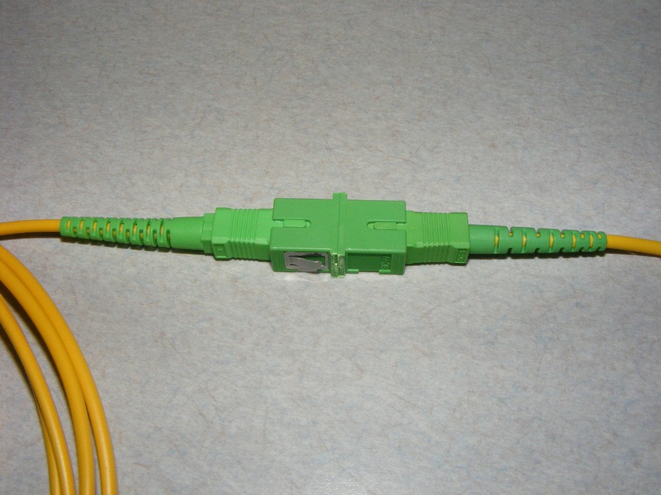
cables installed by others. All the connectors must be GREEN and fusion-spliced to
the longer fibers between buildings or terminating locations! GREEN FIELD
INSTALLABLE connectors defeat their intended purpose and are USELESS for RF signal
transmissions! An SC-APC connector mates to another SC-APC connector in this photo
below.
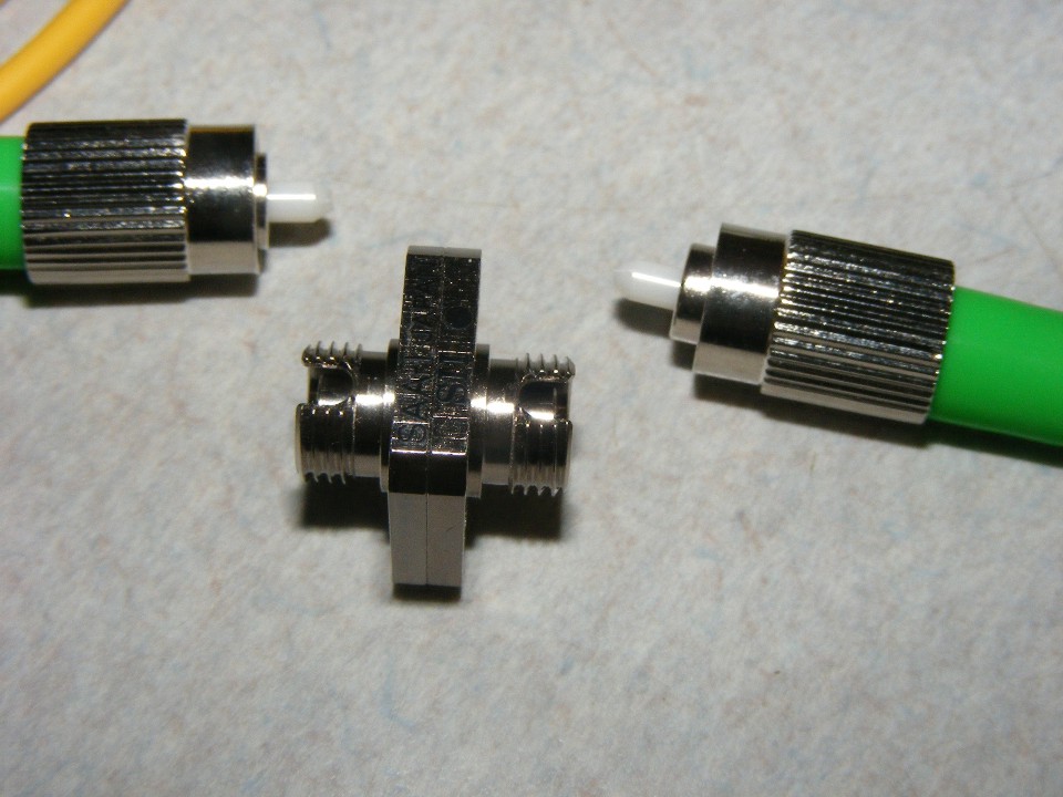
FC-APC to FC-APC connections like these are also usable for analog RF fiber
optic links. Do not over-tighten the threaded rings to the bulkhead as nasty things
can happen, like extra loss due to connector misalignment of the fiber cores. I
measured over 2 dB of additional loss due to a connector like this one that was too
tight.
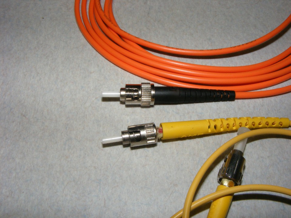
If you find these ST connectors on MULTI MODE or SINGLE MODE fiber in your
system, you will have trouble with ALL RF signals! These types of connectors are NOT
PERMITTED, EVER!!! WHY, the ends are flat and that is how reflections are
created as seen on page 2 of this article.
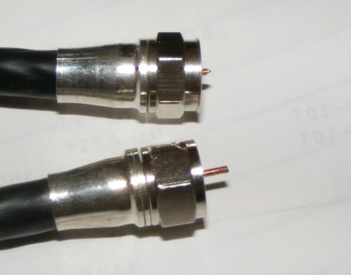
And now that we have made all the fiber connections properly, have you checked your type "F" connectors installed on the RF input to the fiber transmitter or the output from our fiber optic CATV receivers? The center conductor needs to be about 5 mm or 3/16 of an inch long as seen on the connector at the bottom of the photo below. Some cable television equipment has mating connectors that may not work with a short center pin like the connector at the top of the photo below.
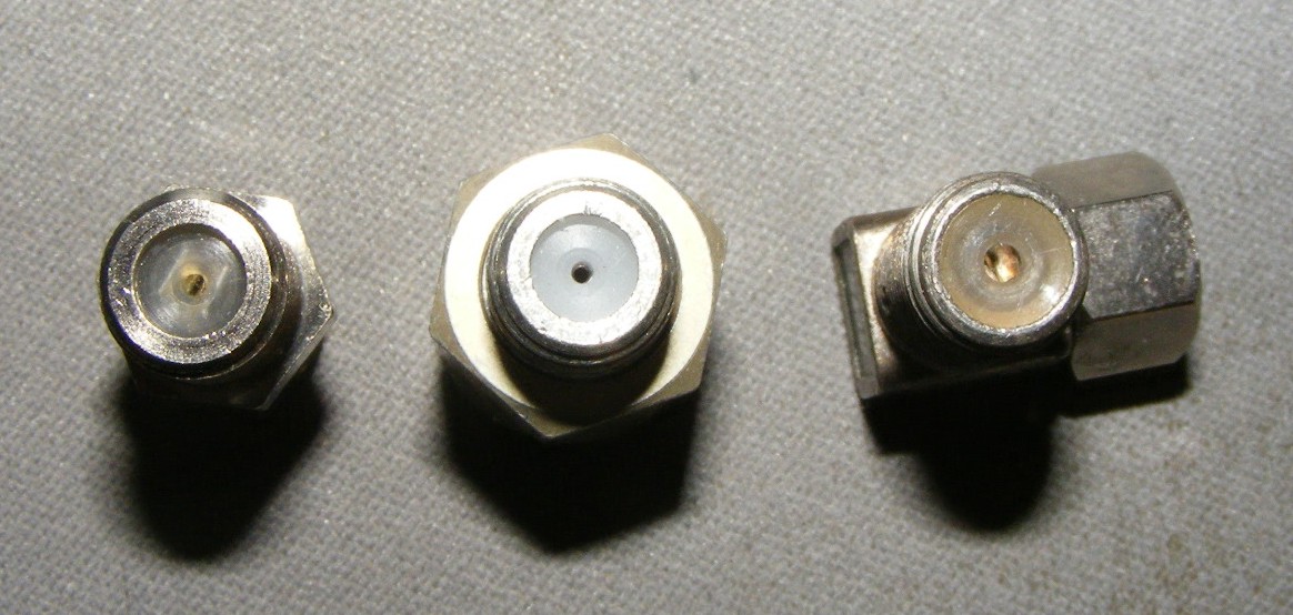
Here is a photo showing some of the different types of female connectors for cable television equipment. The one on the left side of the photo below may have trouble with the short center conductor of the male "F" connector seen above. The one in the middle has the new 1 GHz center pin seizure connection and works the best of all of them. The right-angle connector works fine in systems below 550 MHz, but introduces signal errors on QAM signals most commonly found in cable systems between 550 MHz and 1 GHz.
| RETURN to TECHNICAL ARTICLES MENU | RETURN to Main Menu |