Fiber Optic Fundamentals (Fiber Reflections) - PAGE 2.
Now that the CATV RF signals have been converted from coaxial cable to infrared
laser light for transport via single-mode fiber, we turn our attention to the fiber path.
If you have a fiber optic guy who has worked with digital fiber networks for years
putting in your fiber, you will probably have trouble with your
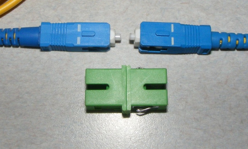
fiber network from DAY ONE! His fiber world has flat-finished BLUE or BLACK fiber connectors in it that are a source of optical
reflections and they will destroy the signal quality of analog RF signals, but are fairly
transparent to digital signals where the laser light blinks on and off. These BLUE
connectors are SC-UPC ultra-polished connectors. The mating surfaces are polished at
a 90-degree angle to the fiber path, causing reflections of the laser light inside the
fiber. Those optical "echoes" are a real problem with RF fiber optic
signals.
Consider the digital laser transmitters for a minute: Light on, Light off - represents Ones and Zeroes for binary data transmissions. This is 100% modulation of the laser light beam. These types of systems may have a "small form-factor pluggable" (SFP) digital fiber transceiver module or a "gigabit interface converter" (GBIC) transceiver with optical output power from 0 dBm to +5 dBm feeding digital fiber transceivers at the remote end of the fiber cable with a sensitivity down to -23 to -25 dBm. With that much dynamic range in the optical loss budget, the optical reflections don't amount to much when it comes to telling the difference between "LIGHT ON or LIGHT OFF" at the digital fiber receiver at the other end.
Now consider the analog RF fiber optic transmitter. With so many analog RF carriers, the total RF input power of all those channels must be considered and controlled to minimize the unwanted mixing of the separate RF channels (CTB & CSO). Instead of 100% modulation possible with digital signals, the optical modulation index for analog signals can be in the range of 10% optical modulation index (OMI) or less, depending on how many signals are to be transmitted. These ANALOG television and radio signals ARE NOT DIGITAL SIGNALS! The laser is NOT blinking ON and OFF to represent binary data streams. There can be combinations of amplitude-modulated, phase-modulated, or frequency-modulated RF signals. With a large number of channels, 3% OMI is common. With this limitation on the modulation, any REFLECTIONS that occur in the fiber path can severely degrade the performance at the receiving end. The reflections cause the light rays to arrive at different times at the optical detector inside the receiver. Remember, the coherent optical signals are the ones that perform best.
Where do these reflections occur? If you have any FLAT-FINISHED optical connectors in your system, you will find out. GREEN angle-polished connectors are REQUIRED in analog RF over fiber networks.
 |
 Angle-polished connectors shown above have reflections (RED arrow) that are absorbed into the cladding of the fiber, not bounced back and forth as in the FLAT finished connectors shown in the LEFT drawing. Most of the fiber signal passes through the connector (BLACK arrow) with a typical loss of 0.2 dB for a clean connection. LC-APC fiber optic connectors are smaller than FC-APC, or SC-APC connectors and will work just fine for fiber optic RF signal transmissions. |
| Now imagine what happens when you try to plug a BLUE flat-finished fiber connector up against a GREEN angle-polished connector. You could damage the ceramic material that surrounds the fiber, but more important is the fact that the fibers at the center of the connector will not physically touch each other as seen in the images above. The air gap that exists between the two fiber ends will have a high attenuation, possibly 5 to 10 dB of optical light loss. A 10 dB optical signal POWER loss will cause a 20 dB RF signal VOLTAGE loss at the optical receiver. Power is a 10 LOG function when comparing two different power levels. RF signal level meters use a 20 LOG function for comparing two different RF signals. |  Angle-polished
and flat-finished fiber connectors do not mix! Make sure you know what kind of
connector is on the other side of bulkhead connectors when building the fiber network.
It is possible to crack or break the white ceramic material surrounding the fiber
doing this. |
The two Optical Time Domain Reflectometer (OTDR) traces below show the results of changing SC-UPC or other types of FLAT-end fiber optic connectors to SC-APC green angle-polished connectors. Those spikes in the trace on the LEFT BELOW are the reflections along the fiber path where fiber patch bays have fiber connectors with flat-ends. The same fiber path is shown on the right showing the fusion-splices and factory-made angle-polished pigtail connectors that were fusion-spliced to the LONG fibers at all locations. Please take notice of the lower losses overall, AND the absence of the spikes that were the reflected optical energy degrading analog RF signals in the fiber optic cable. Replacing the connectors allowed for CATV fiber optic signals to be used on the fiber path, and reduced the optical attenuation on the digital signals on other wavelengths also transmitted on this fiber path. Lowering the fiber connection losses allowed for the installation of the optical MUX and DEMUX that combined the CATV wavelength at 1310nm to the link with existing multiple CWDM wavelengths carrying digital signals (one's and zeroes).
| BLUE SC-PC or any FLAT-FINISHED CONNECTORS | GREEN SC-APC ANGLE-POLISHED CONNECTORS |
 |
 |
Field-installable angle-polished connectors (Unicam from Corning,
FastCAM from Leviton) are for digital data fiber links
ONLY, not for RF fiber links. An actual OTDR trace is seen below where those
type GREEN angle-polished connectors were installed on 680 feet of single-mode
fiber at the United Nations building in New York City. The reflections are indicated as
spikes on the trace and destroyed the quality of the CATV signals. These connectors
require a cleaved fiber to be inserted into the connector where it touches the end of
a short internal fiber. That short fiber is angle-polished at the front face of the
connector but has a FLAT end where the installed fiber touches the fiber imbedded inside the
connector. It is those blunt fiber faces meeting inside the connector that
create
the reflections seen in the OTDR trace below. Even if a matching gel is used, the
signal will degrade over time and will never be as good as a fusion-spliced, factory-made
fiber pigtail with a GREEN angle-polished connector. Their connectors are
usable with DATA NETWORKS, but the GREEN ones are USELESS as the reflection
occurs at the FLAT cleaved fiber interface inside the connector. DO NOT
USE THESE CONNECTORS.
Using factory-made GREEN angle-polished fiber pigtail connectors that are FUSION-SPLICED to the long fibers between buildings or IDF closets is the only way to avoid reflections in a fiber optic network transmitting RF signals over single-mode fiber.
Using a CORE-ALIGNMENT fusion splicer gives the minimum splice loss from 0 to 0.05 dB. The typical loss with that type of fusion splicer is 0.02 dB. Use of a V-Groove fusion splicer is common for ribbon fiber (12 fibers) in the digital data fiber business. These splicers can have losses from 0.5 dB to 1 dB. This is unacceptable for CATV signals and RF signal transmissions for satellite signals.
EVERYTHING on this page is part of rule NUMBER 2 of fiber management.
| Fiber Fundamentals - PAGE 3 | RETURN to TECHNICAL ARTICLES MENU |