David Edgemon - RV-9A at the airport.
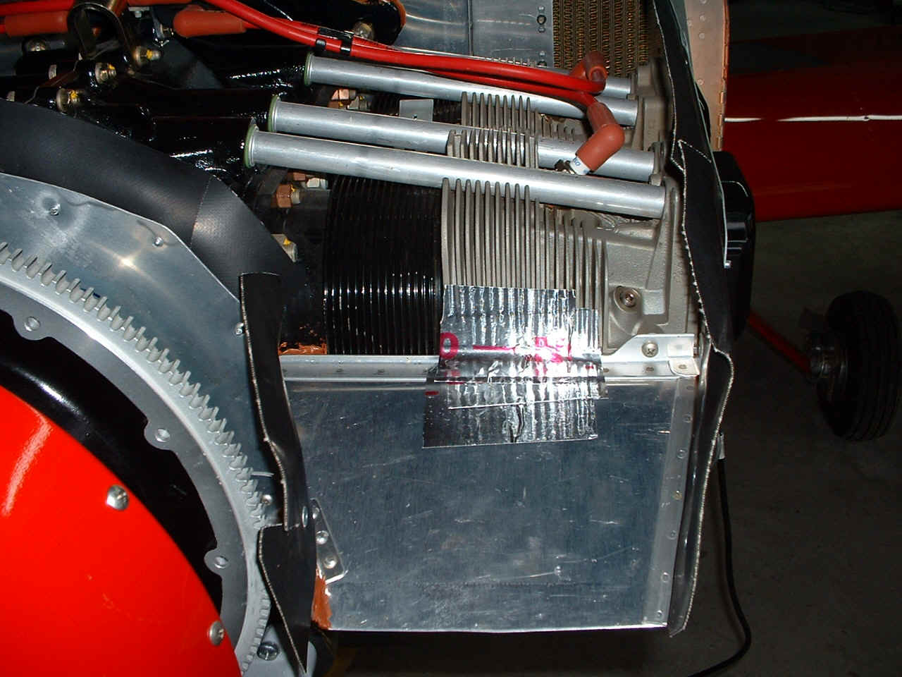
November 27, 2004: Continued -- It is fairly easy
to balance the cylinder head temperatures on the front cylinders by covering up some of
the fins with this thermal tape from Home Depot, Lowe's, etc. The front cylinders
are always cooler than the rear cylinders and therefore need a little bit of "warming
up" by blocking some of the air flow across the front cylinders with this tape.
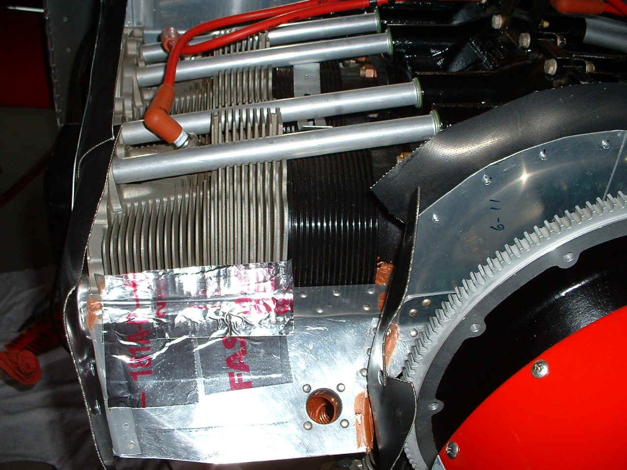
The other side gets the same tape treatment.
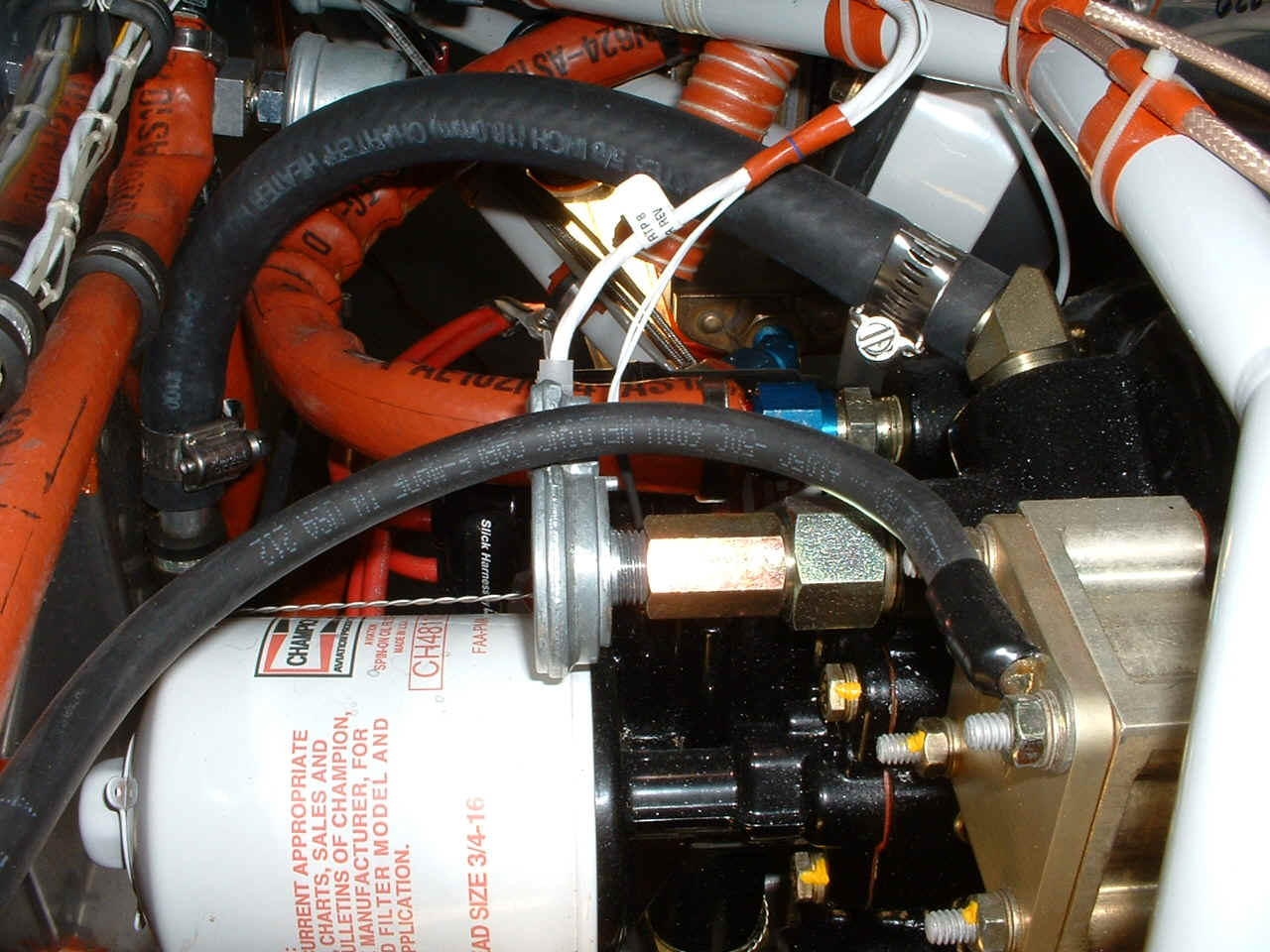
This is the tachometer
sensor from the Van's Aircraft catalog that provides pulses to the EIS engine monitor for RPM measurements. I
have to order one of these! Notice that the BLACK ground wire to the engine goes to
the cover plate over the vacuum pump location since there is no vacuum pump on his engine
(or mine either). David chose the standard oil filter location instead of the right
angle upright mount that I had put on my ECI
Titan experimental engine when Penn Yan
Aero Service assembled and tested it. A reminder, this is the Superior Engine
which David bought from Aero Sport Power.
Both of these engines are after-market equivalents to the Lycoming
O-320-D1A engine.
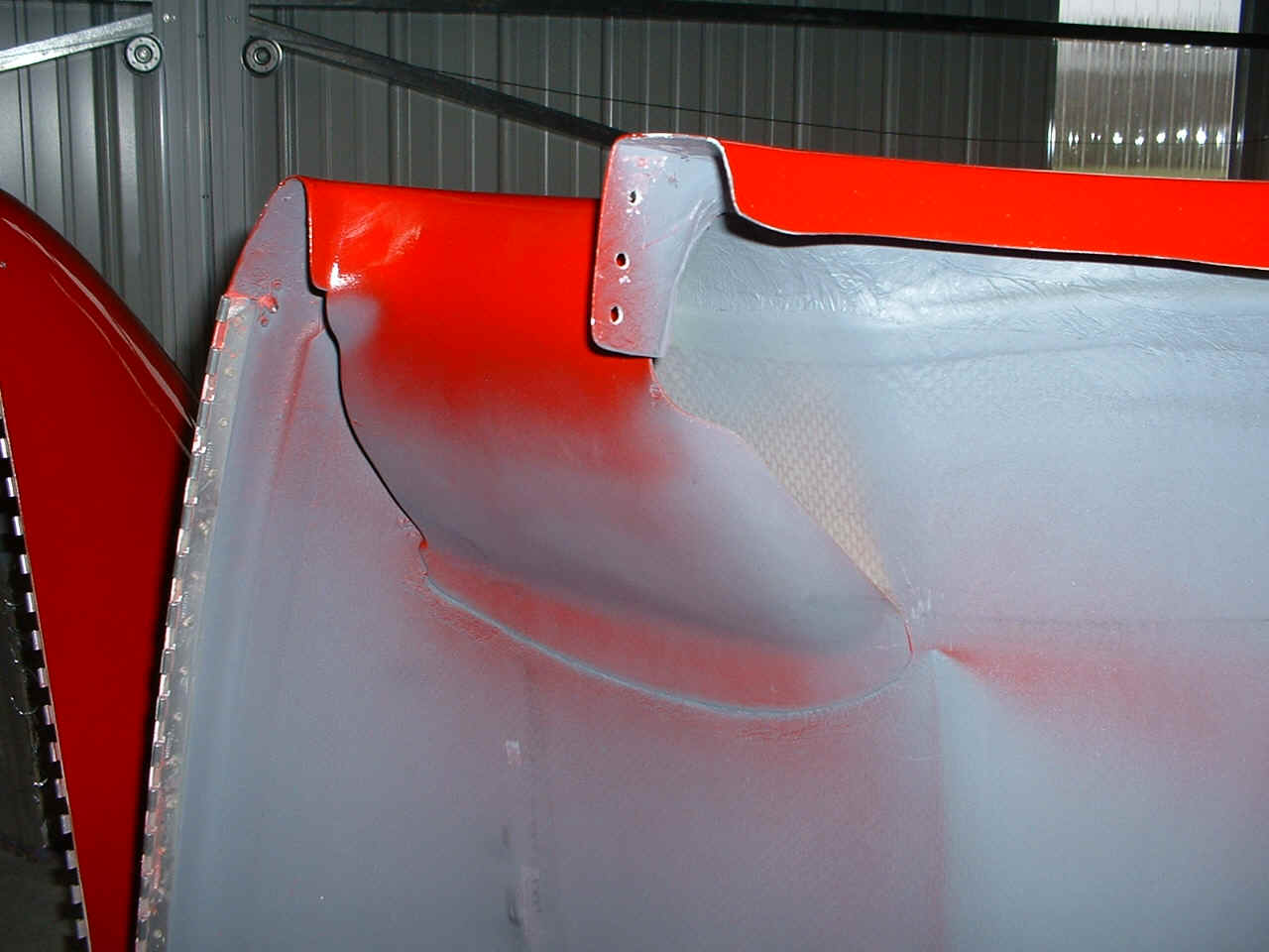
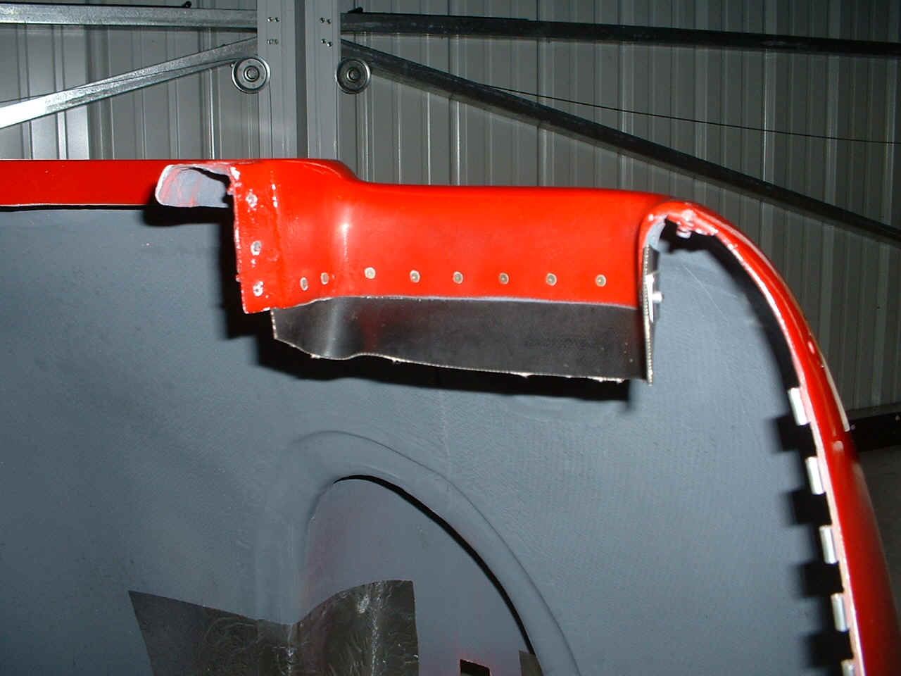
The cowling was the other item of interest to me on this day trip. This
is the bottom side of the TOP cowl showing the cooling air intake for the cylinders on the
right side of the engine. It has three holes for retaining screws that hold the top
section to the bottom section near the spinner. The matching holes in the lower cowl
are shown in the next photo below this one. There are two of these air flow ramps
glassed into the cowl. The ramps are provided in the cowl kit from Van's. The
hinge along the edge at the LEFT of this photo mates with a similar hinge on the lower
cowl which is partially visible at the extreme left side of this photo.
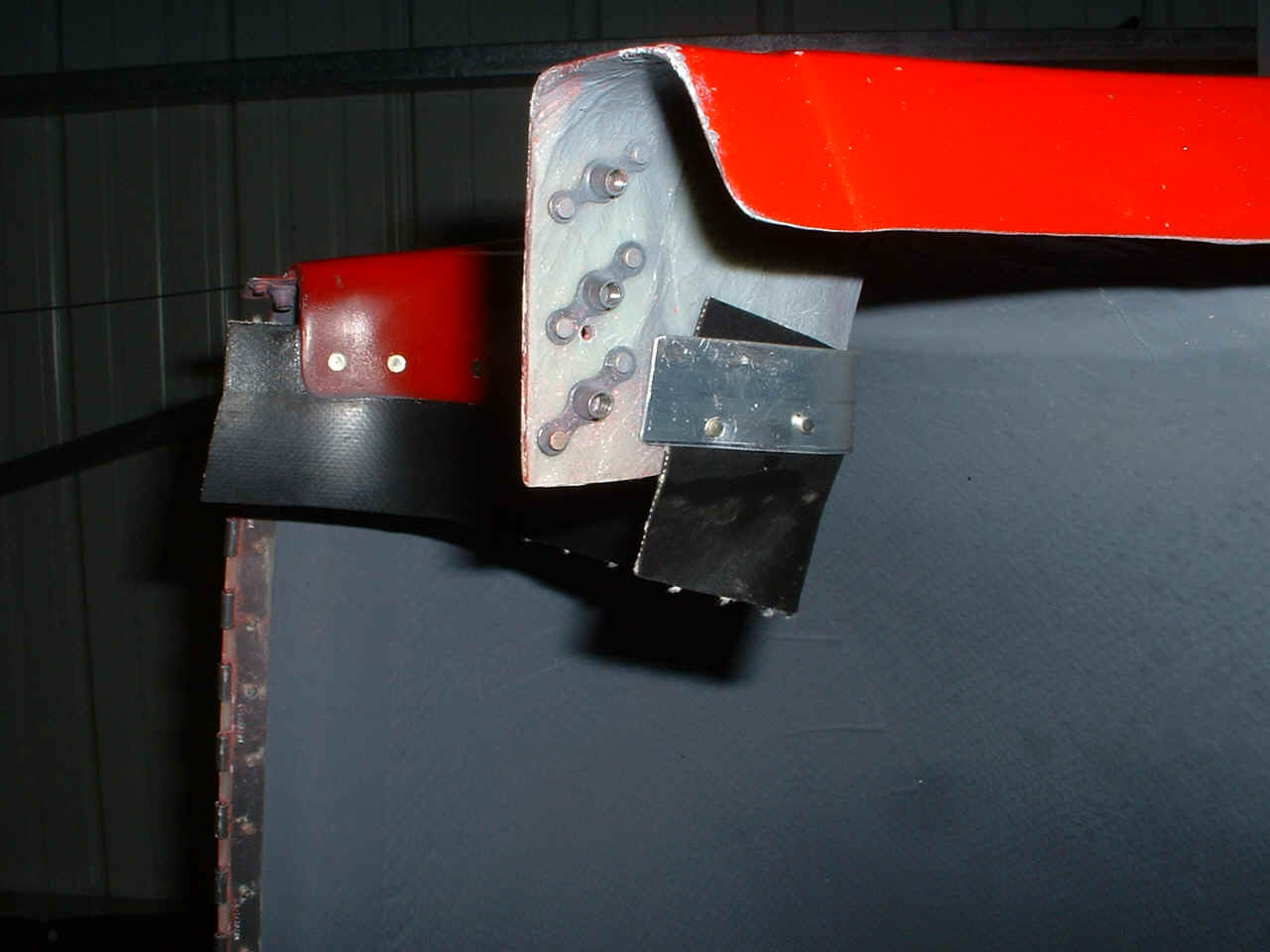
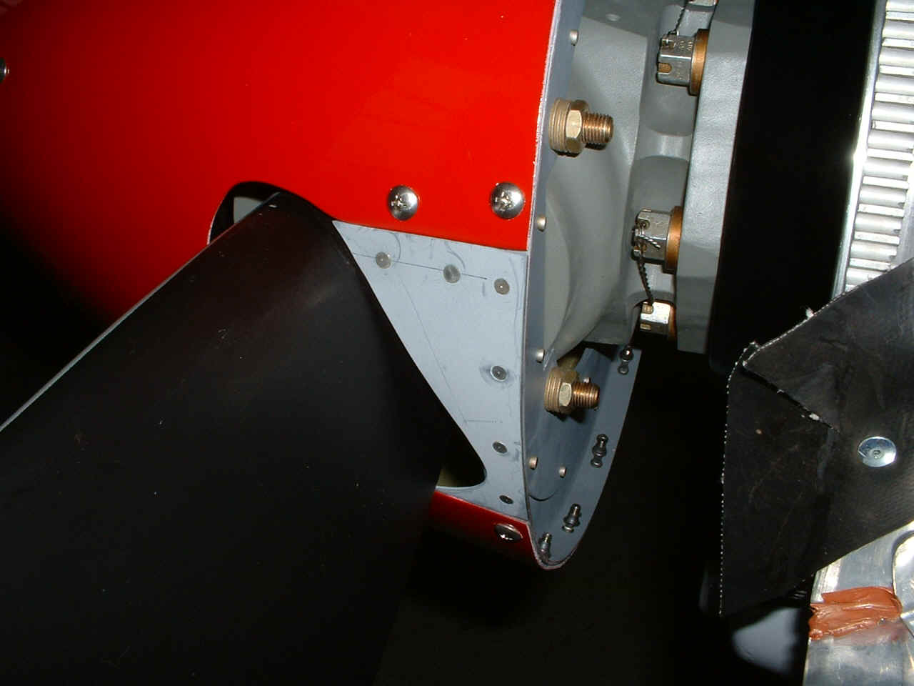
More cowl details. The lower cowl has air seal fabric riveted to it to
insure a clean flow of air onto the ramps in front of cylinders 1 & 2. This is
the right side of the cowl that is in front of cylinder #1. There are also three
platenuts that are hiding on the left edge of the air scoop to accept screws for holding
the upper half to the lower half of the cowl.
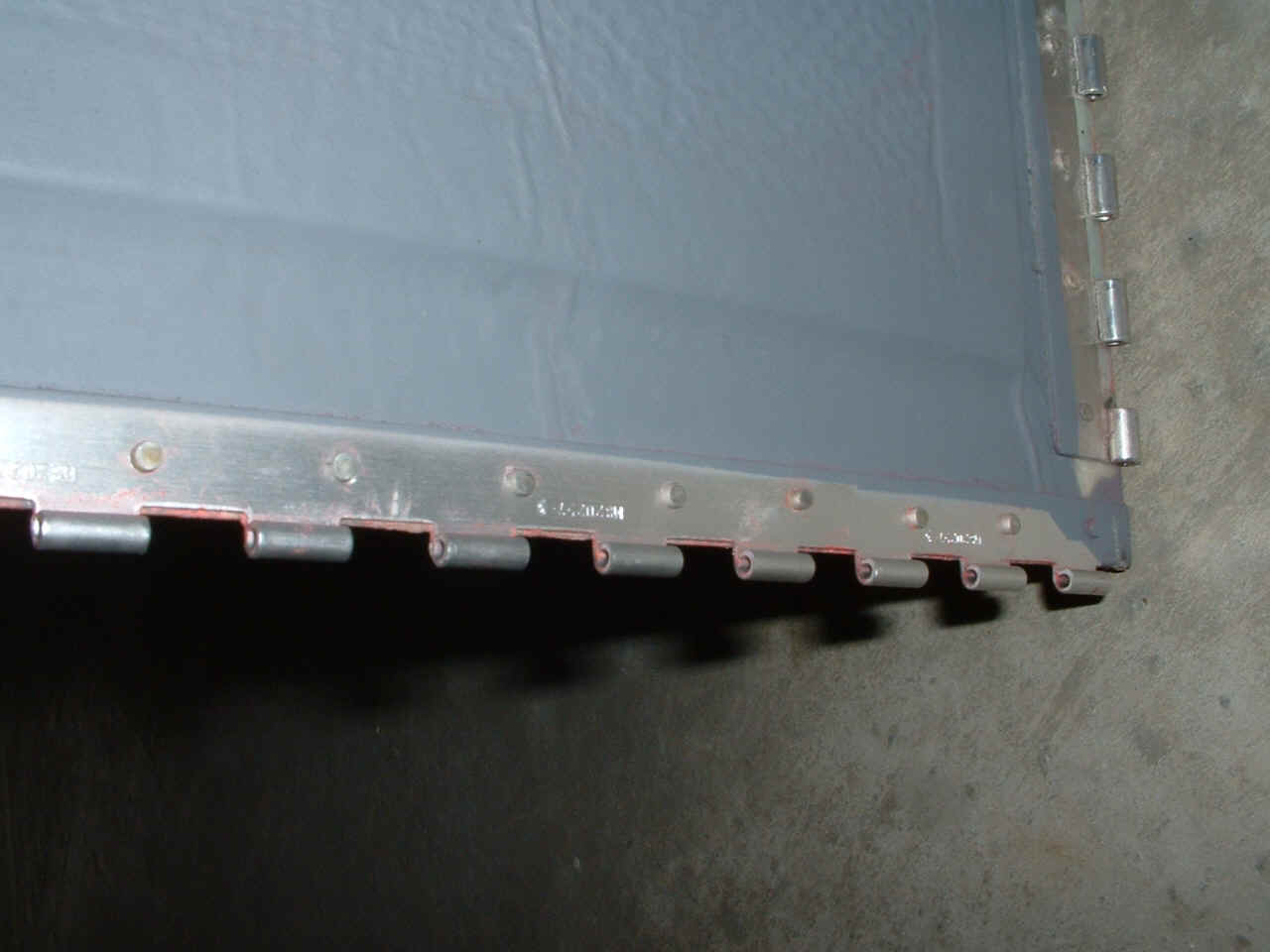
Speaking of platenuts, here they are and a good view of the aluminum doubler
plate that holds the air seal fabric to the air scoop intake area of the lower cowl.
I just got an idea about putting a larger doubler plate here to also add strength
to the three platenuts and run underneath to hold the air seal fabric as well.
This is the hinge along the line where the upper and lower cowl meet. The
hinge at the right of the photo is the one that connects to a similar hinge on the
firewall.
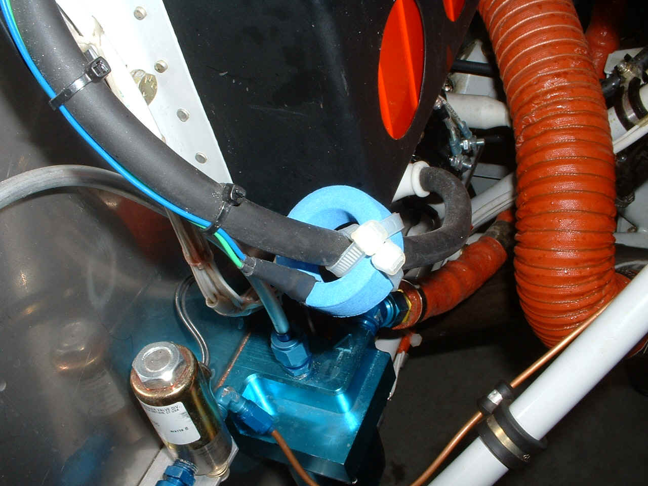
I went back to the main battery cable to check out the mounting of the ammeter
sensor toroid that feeds data to the EIS engine monitor.
The last photo of the day is the detail around the variable pitch propeller
blade on the spinner. David had to enlarge the opening in front of the propeller
blade to allow the full twisting of the blade without pushing against the fiberglass
spinner cone.
| Return to Other RV Menu Page. | Return to Menu Page. |